Hi all,
I'm sure that this topic has been well covered but to save time in search, I have seen soft start circuits that use one or two MOVs that later get shorted by a relay for full power. I'm looking for a simple circuit that is reliable and places to get parts.
My circuit will be powering an old Peavey transformer from a PV .75K amp that produces 2X +/- 53VAC, current unknown but it powers 2X350WRMS power amps. I will be rectifying both sets of windings and then parallelling them for a 500W amp I'm building. I will have 40,000uF of filtering per rail so I need a good circuit to soft start with.
Can someone please help?
Thanks in advance,
Chris
Why an MOV? If you are going to short across it, then a decent power resistor will be fine, and IMHO, probably more reliable.
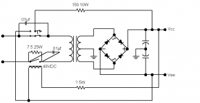
I have built this circuit and added it to several amps. The resistor is an Ohmite 89-Type, aluminum axial, from Digikey.. Very small, very tough.
I show a DPDT switch, with a resistor to discharge the caps. Not necessary in all apps. I also show the relay coil being powered from both rails. Not very efficient with high rail voltages, but keeps current draw even....if these are high-power amps, a 110VDC relay might be a decent idea...less wasted power.
Attachments
The solution will work but have two disadvantages:
1: Slow reset. Sometimes you get a rather short dip in mains volatge, this can create a heavy current spike (if you use a toroid) even if the smoothing caps are charged.
2: Not allowed in Europe due to safety reasons if you mix mains circuit and secondary side in the same relay. If you choose this solution you must use a relay with increased isolation, for instance ELESTA SIRxxx types
Huh? And the spike is smaller with no soft-start?? This sentence makes no sense...perhaps you would care to elaborate...1: Slow reset. Sometimes you get a rather short dip in mains volatge, this can create a heavy current spike (if you use a toroid) even if the smoothing caps are charged.
He's in Oklahoma.2: Not allowed in Europe due to safety reasons if you mix mains circuit and secondary side in the same relay. If you choose this solution you must use a relay with increased isolation, for instance ELESTA SIRxxx types
") We got half the line voltage you all do.
We got half the line voltage you all do.This is a very commonly used circuit...stolen from an 'audiophile' amp. No magic here. It would be nice to find a decent relay, and a high isolation wouldn't hurt, but most of the HI relays are excessively large. If you got the room, then sure... But for me, at this point anyway, any suitable high-current relay of 48V or better seems to be damn near impossible to find.
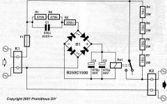
What about this cct. I have made a couple of these and they work great.
http://mitglied.lycos.de/Promitheus/delay_circuit_for_toroids.htm
http://mitglied.lycos.de/Promitheus/delay_circuit_for_toroids.htm
Attachments
Hi.
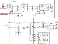
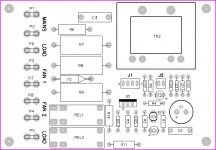
Now it's my turn.This is soft start unit I used in projects with Holton's AV400 modules.The schematic is stolen from Elliott's pages,but I've added some things from a professional unit.
As you see there are two relays.Relay 1 shorts the parallel resistors and he acts in approx. 1,5 sec delay.The relay two acts immediately.In fact he is the main switch and you don't need to use those 10-15A switches.The relays are 12V type.
F2 is a thermo fuse.He blows if Rel 1 fails.The fuse is mounted between the R8 & R9.There must be a contact with them.The best way is to stick them together with a plastic strap.
Q2 is BUZ71.A much less powerfull transistor can do the job very well.I've used this mosfet because I have a whole bunch of them.
Bellow is the schematic and the PCB(in case you decide to build it)
Regards.
Attachments
You can see my implementation of this circuit here:
http://www.diyaudio.com/forums/showthread.php?s=&postid=50187#post50187
Works well so far. I second EchoWars' recommendation to use a power resistor in stead of a MOV.
See ya,
Tim
http://www.diyaudio.com/forums/showthread.php?s=&postid=50187#post50187
Works well so far. I second EchoWars' recommendation to use a power resistor in stead of a MOV.
See ya,
Tim
Echowars,
What Peranders said made sense to me. He is saying that the circuit that you posted will take an appreciable time to reset itself when the mains is disconnected. This delay means that in the event of a momentary mains power failure, the circuit may fail to reset and the soft start action would not be present. Other, more involved (active) circuits may have quicker reset times and hence avoid this problem.
Tim.
Huh? And the spike is smaller with no soft-start?? This sentence makes no sense...perhaps you would care to elaborate...
What Peranders said made sense to me. He is saying that the circuit that you posted will take an appreciable time to reset itself when the mains is disconnected. This delay means that in the event of a momentary mains power failure, the circuit may fail to reset and the soft start action would not be present. Other, more involved (active) circuits may have quicker reset times and hence avoid this problem.
Tim.
Diode posted:
trwh, I like that circuit, and I may well use it on another project. But it is not exactly simple (but it is well done).
Edit: Certainly the power switch and bridge ought to be decent enough to be able to handle turn-on without the soft start, otherwise it is simply poor design. An occasional power dip resulting in the loss of mains voltage requiring the recharging of the bridge and filter caps should not be a problem, and if this is a frequent occurance, then you've got more problems than the need for a soft-start circuit...
Emphasis mine. I tried to provide exactly what he asked for. Start planning for all contingencies and suddenly simplicity is out the window.I'm looking for a simple circuit that is reliable and places to get parts.
trwh, I like that circuit, and I may well use it on another project. But it is not exactly simple (but it is well done).
Edit: Certainly the power switch and bridge ought to be decent enough to be able to handle turn-on without the soft start, otherwise it is simply poor design. An occasional power dip resulting in the loss of mains voltage requiring the recharging of the bridge and filter caps should not be a problem, and if this is a frequent occurance, then you've got more problems than the need for a soft-start circuit...
WOW!
Thanks all for the information. I had seen the ESP design but wanted to see others and get different opinions. Yes, I have also seen to add a seperate power supply for the relay ckt. I will have a 12V PS for my speaker protector already so that's good!
The reason I mentioned MOVs was I worked for a power supply manufacturer and they used MOVs with a relay for their inrush ckt. Also Peavey uses MOVs on a big amp of theirs as well. I just haven't studied the circuit yet.
So many choices!!!! Jeez, next, I want to build a variable limiter.... I can't imagine how many different circuits there will be...
Keep the ideas coming if you wish. I use 120VAC in America though.........
Thanks to you all!
Chris
Banned
Joined 2002
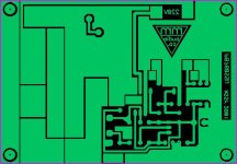
Wow, dangerous pcb.And the PCB.
Bottom layer:
Creepage distance almost zero.
Old thread, I know.
Did you first remove the dust from this thread in order to post? Ok, that PCB was designed back in 2001. Anyways, if you apply the soldermask then there is no fear of jumping sparks between the copper traces. Well, I'm more mature now and my PCBs are more mature now as well.
Edit: the distance between traces was 30 mils. Maybe the low picture resolution makes it look closer.
Ok, that PCB was designed back in 2001. Anyways, if you apply the soldermask then there is no fear of jumping sparks between the copper traces. Well, I'm more mature now and my PCBs are more mature now as well. Edit: the distance between traces was 30 mils. Maybe the low picture resolution makes it look closer.
Last edited:
- Status
- This old topic is closed. If you want to reopen this topic, contact a moderator using the "Report Post" button.
- Home
- Amplifiers
- Solid State
- Soft start circuit