Well, the problem (as probably already mentioned above one way or the other) is that potentials at the points 14 and 15 (schematic from Post #1) are "undefined", resulting in the VAS sranding current "competition" between the positive and the negative VAS sholders, resulting in VAS standing current instability (it will fluctuate).
There are two ways to solve this problem:
1) Add the Common Mode Control Loop (CMCL) circuit, so that you track the VAS standing current and regulate the LTP currents accordingly;
2) Don't use the mirrors - resistor loads make the mentioned above potentials "defined", so the problem is not there any more.
Cheers,
Valery
Whatever the LTP currents, the base currents of Q11,Q12=0. Mirrors, sir!
Not really
")
Ic(Q2) = Ic(Q1) + Ib(Q11), where Ib(Q11) cannot be zero - if its Ic is not zero, Ib is not zero as well.
Change in LTP currents will change the points' 14, 15 potential, influencing the VAS bias and therefore its quiescent current.
The simplest (imho) way to define VAS current(s) is to place RCR circuit between points 4 and 30 (6 and 33).
Or even to connect upper pin of R6 (lower pin of R9) straight to point 30 (33)!
Emmm... those changes will influence many things, but I'm not sure they will solve a "competition" problem.
This dual LTP topology with current mirrors is inclined to common mode instability by design, unless it's equipped with CMCL.
The upper and the lower VAS shoulders (in fact, the upper and the lower halfs of the circuit) start "competing" with each other - the output DC offset stays zero, but the VAS quiescent current starts fluctuating, as in terms of common mode the circuit is not stabilized. VAS collectors either pull at the same time, or push at the same time - quiescent current moves up and down with a period, determined by the NFB lowest time constant (or DC servo time constant in case it is used in the circuit).
You can see it if you build the prototype and monitor the VAS quiescent current...
Same thing happens in fully differential amplifiers - two NFB loops and "undefined" common mode behavior, unless CMCL is properly arranged.
I cannot speak for the late Mr. Slone.Now don't get me wrong here. Why should someone like Randy Slone post something in his book that shouldn't work as intended?
Thing is, I too was trying to build this amp until I found this thread in this page.
Any possible way to make this circuit work with stability?
Are you still attempting to build this amp design? And which one (Slone had several in his book)?
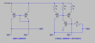
The problem stems from attempting to use current mirrors in the input stage, which do not provide a fixed voltage reference for the VAS. Bob Cordell came up with a method to solve this. Unfortunately, that alone will not produce stable VAS current in Slone's design, the VAS needs a little modification as well. If you want details I can provide them, at least it is stable in simulation. However, I don't know what other problems may lurk in the design. These modifications require additional parts. Not expensive, a couple of transistors and some additional resistors, and changes to a few values. But if you are already have a circuit board you will need to figure out how to fit them in.
I was looking forward to this design mainly.
Bob Cordell used a resistor which connected to colectors of the current mirror to solved the undefined VAS current.
No, it will not help.I was also thinking about a solution like this. Sorry for my crude drawing but will this method work?
See the attachment.
Cordell's method uses an extra transistor and the VAS is referenced to the base of Q3 in the schematic. The value of R4 determines how much control Q3 has over the operating voltage at the VAS input. A lower value gives greater control, but also limits the gain of the input stage, since the IPS is trying to drive a lower impedance. 22k seems to be a decent compromise, midway between the recommended 10k to 47k.
R1 and R2 may not be absolutely needed, but they do provide several benefits. These emitter degeneration resistors, if matched, help alleviate any variations in Q1-Q2 due to mismatched beta or VBE characteristics. The effectiveness of the current mirror is limited by how well matched those transistors are. These resistors help linearize the response. Also, the combination of resistor and transistor in this application is quieter than a transistor alone, though that might be irrelevant compared to the noise of the input transistors. And, since we are setting a reference voltage for the VAS stage, any voltage drop across R1-R2 will be added to the VBE drops of Q1-Q2+Q3. That will turn out to be useful.
Attachments
correction
Cheers, E.
Sorry, above link is broken. This is the correct one: MCP A so called common mode control loop (CMCL) does the trick. (see Q5, Q10, Q11 & Q12).
Cheers, E.
I fully agree with Edmond (Cheers Edmond  ) - in this kind of design, where the positive and negative halves of the front-end "compete" with each other, CMCL is the way to go. It's practically a common-mode servo, tracking the VAS current and regulating it via a common mode negative feedback.
) - in this kind of design, where the positive and negative halves of the front-end "compete" with each other, CMCL is the way to go. It's practically a common-mode servo, tracking the VAS current and regulating it via a common mode negative feedback.See post #190 in the "Bryston 4B SST clone" thread - this method works very well too. Basically you make the VAS transistor one leg of a current mirror and use the other leg to set the VAS standing current. First saw it used by Giovanni Stochino in his "300uS Power" article in Electronics World April 1997 but not sure if he invented the technique. Electronics World sold pcbs for the design and I never saw any complaints or discussion so it must have been a robust amp. Works fine for me too, as you can see in the thread I referred to.
- Status
- This old topic is closed. If you want to reopen this topic, contact a moderator using the "Report Post" button.
- Home
- Amplifiers
- Solid State
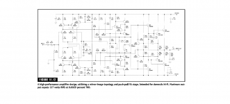
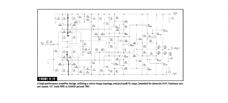
- HEEEELLLPPP : M. Randy Slone Mirror Image Topology Construction - Troubles