Hi all,
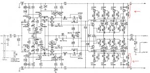
I have an Anthem Amp 2 power amplifier for which I upgrade several caps. After the upgrade the resistors marked in red in the schematic are over heating. I suspect its a bias issue. Can anyone help me with instructions on how to set the bias for this amp. There is a bias potentiometer but I do not know what I need to measure when setting the bias.
Any other ideas why these resistors are over heating?
Thanks
Ronen
Attachments
Hi Ronen,
Nothing to worry about. Those resistors are essentially series connected between +-80v supply.
Current flowing through is 53mA, leading to 2.13W dissipation for each resistor.
The resistors are rated at 3 times this value so not really a problem.
Check the output, it should be close to 0 volts.
If you only replaced some capacitors then biasing of output transistors shouldn't have changed at all from the manufacturer's settings.
Regards,
George
Hi George,
Apparently something is wrong since the resistors in one channel are blown. I disconnected power before the other channel was toasted. The resistors got so hot that I could not touch them.
I checked for the voltage at the output and it was 0.019v. The transistors did not get hot and I did get sound from the speakers although I cannot tell if it was distorted or not since I used small test drivers.
Maybe its not the bias but something else. Any other ideas?
Regards,
Ronen
I see no reason to change c7 and c8 to something better than cheap ceramic or polyester caps.
Wimas MKP10 are overkill for the position in my opinion.
Q14 and Q13 serve the secondary function to protect the output stage in case of short-circuit or abnormally low loads.
FKP2, 330pF should be fine, although the original NPO ceramics should be just as fine.
Were all four of the resistors overheating or just two of them?
As far as I remember all four resistors were heating.
One more thing I just remembered, I also replace the 0.1uf (C14) in the Zobel network.
I don't have the amplifier infront of me right now but I will check again tomorrow.
I will try to return the original 330pf capacitors this weekend to see if it makes a difference.
One more thing I just remembered, I also replace the 0.1uf (C14) in the Zobel network.
I don't have the amplifier infront of me right now but I will check again tomorrow.
I will try to return the original 330pf capacitors this weekend to see if it makes a difference.
They should do if the reason was oscillation.......The transistors did not get hot
You might want to check for a bad soldering joint or a unintended short circuit.
Hi George,
The Zobel resistor is not over heating. I verified last night that all 4 resistors are over heating. It must be oscilations. I can not think of anything else. I will try to replace the 330pF (C13, C16) to the original NPO capacitors in hope that this will fix the proble. I will get to it this weekend.
Again I appreciate all you assistance.
Ronen
They should do if the reason was oscillation.......
You might want to check for a bad soldering joint or a unintended short circuit.
Jan,
In case of oscillation what can I expect to hear on the speakers? Should I be getting sound? maybe distorted sound?
I still trying to figure out what's wrong.
Regards,
Ronen
Everything from motor boating to nothing. Depends on how the amplifer oscillates....In case of oscillation what can I expect to hear on the speakers?
Use the old trick by inserting a 40W light bulb in series with the Mains AC. That will limit the possible power draw while you check the amp.
Do you have access to an oscilloscope? Best way to check for oscillation!
As stated in post 2 the resistors are rated 6W and should easily handle the 80V from rail to speaker output. Even if speaker output did go to on of the rail voltages, they should still be able to handle the Current (hot but lasting). Oscillation shouldn't burn them without other components also got hot/burned - you stated that output devices didn't get hot.
Try the light bulb trick (with no input) and measure + and - Rail voltages and the output. Carefully feel if any other components in the output section gets warm.
Hi Folks,
I worked on the amplifier last night. Using a 40w light bulb I checked all components for overheating and found no problm. This and the fact that the power resistor between the volvate rails are raised from the PCB about 5mm led me to the conclusion that this might be their standard operating heat. After all 2w hear disipation on such a small device can lead to considerable heat (Jan, the light bulb trick is definitly a keeper!).
So I said lets try to operate the amplifier for a period of time and see what happens. Indeed the amplifier operates great. No DC at output, great sound and all.
One thing I did notice is that the heatsinks on one channel do get considerably warmer than the other channel. Not too warm but definitly warmer than the other channel. The heatsink on the other channel is almost dead cold as if it is not operating, although it works OK. This leads me to the conclusion that the bias is not set the same on both channels. Anyone of you knows how to measure and set the bias on this amplifier. I guess the bias is set via the potentiometer on the board but I have no idea where to measure it in order to set it.
Thank you once more for all your help. I have leaned a lot from you. Great forum indeed.
Ronen
Not knowing the exact specs on your amp, this advise may help you.Anyone of you knows how to measure and set the bias on this amplifier.
Measure the Voltages across each of the pos. and neg. output Emitter resistors f.ex. R60 and R63 (0R47) on both channels, and list your measurements here. You could expect to measure anything from a 10-50mV.
Do this measurements with no input and after the amp has warmed up for say 20 min.
Do not adjust the Bias pot yet.
Hi Jan,
On one channel (the one that's warm) I get 11-12mv for the emitter resistor pair of the trasistors connected to the voltave rails and between 4-5mv for the emitter resistors of the transistors connected to the output+.
On the other channel (the one that's un-naturally cold) I get 4-5mv for the emitter resistor pair of the trasistors connected to the voltave rails and between 0-1mv for the emitter resistors of the transistors connected to the output+.
Does this makes sense? How would you go on to adjust bias?
Thanks
Ronen
This gives you a Bias Current of app. 10 mA through each output device. Quite low, however if the heatsink gets warm (not hot) this could be the correct setting.On one channel (the one that's warm) I get 11-12mv for the emitter resistor pair of the trasistors connected to the voltave rails and between 4-5mv for the emitter resistors of the transistors connected to the output+.
This channel almost run in class B with crossover distortion as a result.On the other channel (the one that's un-naturally cold) I get 4-5mv for the emitter resistor pair of the trasistors connected to the voltave rails and between 0-1mv for the emitter resistors of the transistors connected to the output+.
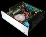
I found this small picture of the amp on the net. The heatsinking is not massive for a 2x200W amp, so if the bias setting of the warm channel makes the heatsink warm (I assume that you have no problem holding your hand on the heatsink), my advice would be to adjust the Bias of the"cold" channel to the same values as the warm.
Adjust Bias while measuring across the output 0R47 resistors to 4-5mV (the same as the warm channel). Wait and keep adjusting to keep the Bias to 4-5mV once in a while until the heatsink has same temperature as the other. It can take up to 30 min., so just be patient.
Attachments
This gives you a Bias Current of app. 10 mA through each output device. Quite low, however if the heatsink gets warm (not hot) this could be the correct setting.
I have set the voltage to as high as 17mv without the heatsinks getting too warm. Seems like the amlifier has no problem with this and it does sound better. What would be the typical emitter resistor voltage in an amp of this design? Is it safe too leave it like this if the heatsinks are not warming up too much?
I have also sent an email to Anthem technical support in hope to get some guidance from them.
- Status
- This old topic is closed. If you want to reopen this topic, contact a moderator using the "Report Post" button.
- Home
- Amplifiers
- Solid State
- Anthem Amp 2 debugging help