don't be sorry for not being precise in your selection of components. There is no reason to appologise.
But, be unambiguous when you tell your readers what you recommend.
As you can see "match transistors" means something completely different to different people.
"What you put in is what you will receive at the other end" On one amp I did not bother to closely match devices ... amp worked (well ??), but Re voltages were less than ideal ( 15mv , 18mv ,14mv). On newer amp, just using a DMM selected 16 out of 30 devices that were "close" .. now ALL Re's are 15mv
") I do not think this made the amp sound better but it might be more reliable in the long term.
I do not think this made the amp sound better but it might be more reliable in the long term. Just a consideration when building a high powered amplifier with many paralleled pairs.
Input devices also follow this line of thought. If you can find 2 that are "close" with the DMM you will have a output offset of <10mv BEFORE having to adjust a trimmer. This actually MAY influence the final sound .
OS
Last edited:
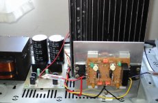
I am still playing with the Troyan..now playing with a voltage regulator
Enjoy the video and the picture:
YouTube - Supply, part 3 - Still playing with the regulator
regards,
Carlos
Enjoy the video and the picture:
YouTube - Supply, part 3 - Still playing with the regulator
regards,
Carlos
Attachments
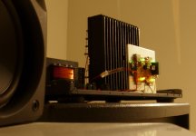
I have discovered the way to make it sound awsome
Interesting.... a non standard modification that may drive technocrats crazy... well..they will never know..they are not builders.
Now it is playing with astounding, awsome superior sonics.
Will inform only to builders.... to avoid troubles...the modification is really crazy.
aahahahahahah!
regards,
Carlos
Attachments
Carlos,
I am not one of the complainers. Please send me all of your modifications. I think I will put this together. I have about 32 nice 100 volt caps and some nice 1kw trannies.
How much welding cable do you think I will need? Joking here.
I also have some 10 nice Rifa 450 volt oil filled caps if anyone is interested. They are real nice. It takes a slew of bridge rectifiers in parallel to charge them.
Tad
All i know from this amplifier was posted Azmi....i cannot remember details
So, the effort for you to read will be the same effort for me to read.
Please, give a good read into this thread in advance to move... this amplifier is not easy.
I am very busy with the new amplifiers to be released, so, i will be happy if you do some effort to read, avoiding me to read the thread to remember and then go to explain you.... do not make too much sense if you can read by yourself saving from uncle charlie some effort and also saving my time and energies... as i have already spent a lot creating it, simulating it, building it and testing it..not your turn folks.
I am glad about your interest friends, but this amplifier was posted so long time ago that i cannot remember exactly....reason why i have posted all things that happened.... the thread is the memory for us..... alike you dear Norazmi...i will have to read the thread entirely to understand it deeply... as i said...i'm doing other things...i would like to be free to finish the stuff i have to do.
Modifications are easy, two parts to change..so...first build it..then after built i will inform you what parts to remove and change value.... will not inform in advance..no way.
regards,
Carlos
Last edited:
Adding a Busbar
Carlos,
Congratulations with your new design. I trust that the builders will enjoy this one as much as they did all your previous designs.
I would like to make one recommendation in that you remove the soldermask from the power lines so that the constructor can solder a copper busbar (see attached picture).
I have found this necessary on high power amps laid out this way. as there is a considerable voltage drop across the PCB track from the first to last transistor and you find the first works harder than the last.
Kindest regards
Nico
Attachments
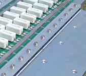
Here is a better view
Nico
What is the bar material?
Here is a better view
Nico
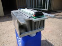
OMG!!! Thats monster Ampppp....
What is the bar material?
It is solid copper cut from a sheet 3mm wide x 1.6 mm thick. However some designers would recommend running a star positive and negative supply directly from the capacitors, which I would think is still better, but it does not look very nice.
Voltage drop on power trace
Nico,
I have never really given much thought to power trace voltage drop. You definately have something here with a very high output amp. Feeding the power trace in the middle would also be helpful. I will give this some consideration when I start constructing the heatsink and chassis layout
When being fanatical about amplifier projects this is just another nice thing to add in. In differentiation amongst the outputs will show up somewhere.
Thanks Tad
Hi Carlos,
in this particular amp I have to pass currents of 56 and more amperes. This can make a hugh difference in powewr dissipation/ It was only a thought. Have you check what is the peak current that you may pass, assuming it is an instantanuous current. Perhaps 10 amps, very probably more?
in this particular amp I have to pass currents of 56 and more amperes. This can make a hugh difference in powewr dissipation/ It was only a thought. Have you check what is the peak current that you may pass, assuming it is an instantanuous current. Perhaps 10 amps, very probably more?
I had an interesting experience when testing this amp looking for speakers. I asked the salesman what is the most powerful speakers he has for full power testing and he recommended some Rockford fosgates.
I said to him, this is a pretty powerful beast and he confirmed that there is no better speaker available for the job.
I asked him to connect some wires to it and insert it into the ac mains wall outlet - he looked at me as if I was mad. But I told him if they play a good 50Hz note for some time I will take two.
He refused my test and I told him, his speakers will not do the job.
- Status
- Not open for further replies.
- Home
- Amplifiers
- Solid State
- Dx Troyan, a 650 watts channel amplifier.