This is you can criticise.... it is terrible!..awfull!...ridiculous!
") But this is a helpfull hand.... a movement of goodwill..... an intuitive, old style, hand sketch, the board made using pen and paper... an idea..a suggestion, something may help...and... WHAT IS BETTER... people will try to make it better (not difficult to do it better..it is awfull!) and this gonna be good to everybody, including me.
But this is a helpfull hand.... a movement of goodwill..... an intuitive, old style, hand sketch, the board made using pen and paper... an idea..a suggestion, something may help...and... WHAT IS BETTER... people will try to make it better (not difficult to do it better..it is awfull!) and this gonna be good to everybody, including me.
Can you, dear friends.... make better than me?
Errors?....of course there are..always have...humans does that....me human..so..i can do that too.
regards,
Carlos
But this is a helpfull hand.... a movement of goodwill..... an intuitive, old style, hand sketch, the board made using pen and paper... an idea..a suggestion, something may help...and... WHAT IS BETTER... people will try to make it better (not difficult to do it better..it is awfull!) and this gonna be good to everybody, including me.Can you, dear friends.... make better than me?
Errors?....of course there are..always have...humans does that....me human..so..i can do that too.
regards,
Carlos
Attachments
It is a HiFi audio amplifier, but of course you can use it as Public Adress too
Can operate from 20 volts symetrical supplies or even lower voltages, have only to readjust bias, you can use other transistors when using lower voltages, alike 35 volts..you can use BC557 in the input, you can use BD139/140 as drivers and VAS, you can use TIP41 and TIP42C..... 2N3055 and 2N2955.... MJE3055 and MJE2055..the ones you have, the ones you want.
Reducing voltage you should reduce the CCS current to drivers....also you can reduce electrolitic condensers insulationg voltage, also the quantity of power output devices.
Obrigado por usar a minha lingua...muito gentil de sua parte.
Thank you by the use of my language..this was very kind from you.
regards,
Carlos
Minimum usefull impedance for Fokker and Troyan is 3.5 ohms
So, it is not good to work using 70V transformers, also not good for 1 ohm load.
I mean, not good to use the old style to connect 70V transformers to distribute audio for several speakers, alike Airport, Restaurant and Hotels..it is a home amplifiers.
Of course can operate using 70 volts symetrical supply.... a very few adjustments may be needed, without replacement of parts.
regards,
Carlos
Last edited:
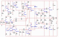
I have already posted the schematic having part numbers on it
 was a pdf file published in post .
Here you have once again.
But i think i will change the Darlington Vas to a single transistor VAS... seems sounds better and waveform is also better.
You see the way i use to learn..doing!..... i found two stage VAS better in several amplifier..in this one produces more 3 volts in my output without clip...but only power...the waveform is worse with the darlington VAS...and exactly the opposite compared to our spectations, the old, ancient and not very modern single transistor VAS, in this amplifier, is performing better...i will check this all day long.
And then come the theorists to say the double transistor, naturally other than mine double VAS, sounds better... that a " correct implemented design works fine "...ahahahahahah!.... their designs naturally!... i cannot appreciate them..they go out from the reality... simulator minds they have.... despite can have good intentions and be skilled (have studied a lot of theories and memorized them)..they are enemies of good sound reproduction..as goes believing without test their beliefs.
regards,
Carlos
was a pdf file published in post .Here you have once again.
But i think i will change the Darlington Vas to a single transistor VAS... seems sounds better and waveform is also better.
You see the way i use to learn..doing!..... i found two stage VAS better in several amplifier..in this one produces more 3 volts in my output without clip...but only power...the waveform is worse with the darlington VAS...and exactly the opposite compared to our spectations, the old, ancient and not very modern single transistor VAS, in this amplifier, is performing better...i will check this all day long.
And then come the theorists to say the double transistor, naturally other than mine double VAS, sounds better... that a " correct implemented design works fine "...ahahahahahah!.... their designs naturally!... i cannot appreciate them..they go out from the reality... simulator minds they have.... despite can have good intentions and be skilled (have studied a lot of theories and memorized them)..they are enemies of good sound reproduction..as goes believing without test their beliefs.
regards,
Carlos
Attachments
Last edited:
I want to let this clear to the ones land in a thread without read since the first
post... these ones does not know what is going on, and may think i love V/I limiters....when i hate them..... was made to a friend and to the ones likes the stuff...mine was tested and disconnected..the Fokker amplifier has not V/I limiter, also my other amplifiers have not.
You use the way you want..... but build something...or my amplifiers or others, do something usefull for yourself and our communitty..help us to have DIY designs, construction and comments..the way we all like, alike the magazines use to do.... we have too much consultants and reviewers..they are needed...but they are not on topic....the main forum topic is Do It Yourself!
About our thousands of Consultants......some of them, a very few in quantity... thanks God, seems to be undercover critics using their rigth to be in a public forum being nasty and sadistic... pretending that wanna help to bother you officially... and protected by the administration that do not want to see some non obvious offenses not to take the risk to be unfair..this is good...also this is bad.
This makes people alike me...that works for the forum to be feeling bad taste inside the mouth and to think seriously to abandon the forum...alike several others did...and they continue..so the natural selection that will result is not interesting to the forum in the long therm... These last couple of days was peacefull.... let's see what future will bring with the next blitzkrieg.
regards,
Carlos
Last edited:
Sorry, i am feeling myself confused..those last weeks the good into the scope
was good to the listening tests..because these past weeks i was working only with the Dx Blame ST.
But this ones is the opposite...i am watching the waveforms and i can see a little bit better to the darlington VAS... also a little bit more power...more dinamic power..but sound is not so good as the single VAS.
Really.. this confirms old beliefs i have... sadly or gladly as i am confused, because this means we cannot follow rigid rules..sometimes enhanced VAS is better, sometimes not.
My preference is the bootstrap sound...but i will keep the CCS because has an appeal... people loves that tecnocracisms...so, they will aprove and some will assemble...one assembling then i will be paid, as the cost to production was cheap to me.... i had pleasure doing..so...not sweat and tears.... low cost means the need of low payment...one building is enougth to me.
One Brazilian will do first...as usual....because they are simple folks...they do not need new parts or ordered special boards...they use to do using what they have..when others have to order and wait the parts arrival.
regards,
Carlos
Last edited:
The Troyan can operate from 12 volts to 120 volts symetrical
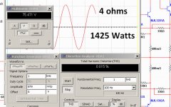
So you will have power going from a very low level, around 25 Watts to 1450 watts rms each channel.
This allows you to assemble with the supply you have and power output transistors will depend the supply voltage, and this will be reflected in the ouput power.
Distortion can be low as 0.004% THD when operating with 100 volts..... go to 0.015% when operating with 120 volts ... so...you can have more than 900 watts each channel with a very low distortion.
It is using CCS to the differential, CCS to the VAS, using darlington VAS and using CCS to the drivers, one CCS to each one of them.
This turns the amplifier a monster of power, delivering enormous peaks of current, that will drive your speakers (I hope you have more than one) to maximum excursion, not matter how hard they are to move.
This amplifiers was assemble and playing for a long time... it is stable and produces amazing sound... 20 kilos speaker enclosures, even having rubber feet, is moving in my room, so huge is the speaker vibration in high power.
This the real "Universal" amplifier...because can work with the supply you have, the supply you found, the supply you like.
CCS to drivers was used in Electrocompaniet amplifiers... what does?... makes bass punch huge, more controlled and reduces distortion.
To be released July, 17 .... for a while two guys are preparing boards layout... Sakis and Metal.
I will accept others producing boards too...no more Dx Corporation main layout designer..because when the main designer resigned..the Corporation almost stops operation.
regards,
Carlos
Attachments
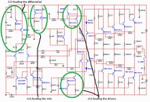
Reason why i am using CCS to the drivers
Main reason why is that Electrocompaniet have used.... and they are very good designers... and i use to copy the good ones to be one of them (one day!)
Technicall reasons in my understanding:
Speakers use to have impedance valleys...in some frequencies, they use to offer to the amplifier a very low impedance and this is helped by the passive crossover.... also you may want to connect your amplifier into 2 ohms impedance and want it not to loose too much power compared to 4 ohms speakers... you want the opposite..you want to have more power.
The main idea is to provide more current to the drivers, a reserve of current, much more than needed, to face extraordinary sittuations.
We can increase driver current reducing it's emitter resistances, beeing floating ones or beeing the standard two resistances, one to each emitter and connected to the output line.....BUT this creates a problem too..when you have increase of current (dinamic operation and iddle operation) you have increase of voltage drop over these emitter resistances.
This increase of voltage drop will decrease the voltage from colector to emitter, reducing the voltage swing and of course, the consequent current swing sent to the output transistors.
The use of CCS, having 20 to 30 mA,will provide a fixed and much more stable voltage to feed the drivers...not having that resistance there, as we do not use resistances anymore, the voltage drop will not exist..so...all voltage swing..and current swing (or almost) will be sent to the drivers.
We perceive that as more punch, in special in low frequencies and in low midrange frequencies where you have drums and some voices....more power to the amplifier, more stability in the operation.
Test this by yourself in your amplifiers..this is good to all amplifiers... Electrocompaniet solution
regards,
Carlos
Please, read the thread dear Black
No boards for a while..will not have boards to sell..only layout to yout to etch.
Board layout is beeing prepared.
Schematic may be the final one...but, as i told, will be released july, 17 (read the whole thread)..till that dead line i can make improvements.
regards,
Carlos
No boards for a while..will not have boards to sell..only layout to yout to etch.
Board layout is beeing prepared.
Schematic may be the final one...but, as i told, will be released july, 17 (read the whole thread)..till that dead line i can make improvements.
regards,
Carlos
My good friend, Dx United Kingdom, Mr. John Blackburn, our forum member
My dearest friend John Blackburn.... i will have a cup of tea because of your visit in our thread...a pleasant presence you are.
Yes.... and can do it with clean undistorted unclipped audio... a continuous power, not an instantaneous small time burst of power.... the monster...the hell hammer... the thunderstorm soul...the Thor Hammer hitting the skies...deep throat of devil in the abissal deep of ocean.... at least in theories....so...you see..how distance are the theories to the reality.
ahahahahaha!
Crazy things...i do agreed.....but it can work from 12 volts (25 watts at 4 ohms) to 120 volts symetrical (1500 watts at 4 ohms.... 750 at 8 ohms).
And this huge power, in the reality depends on a 3000 watts supply to each channel..this means 2 enormous transformers to each channel.... 4 huge transformers inside the same case for a stereo.... 2 enormous 60 centimeters heatsinks... square section that would be something alike a tunel to have them inside would be 18 centimeters each side.... this animal would suck 60 amperes from you mains (will melt your wires)...will need auxiliary power, or special wire from your Electrical company... or a generator.... the heat generated would be the same as a 6Kw electrical heater..these ones use resistance that turns red and have a reflector behind as a mirror to send heat to people...these ones used in Alaska or North Pole.... that animal should need 75000uf/160volts condensers to each side of your supply...total of 150 thousand microfarads to each channel.
These specifications are simulator specifications... real life you cannot afford to build that monster... real life, the power will drop because the supply voltage will drop too... real life, the EMF from the speaker will not let all that power be reproduced...real life you would not be in the same place the monster will be working because of heat.... real life you would need two guys to transport that monster... no shelf will be good to accept that weigth...the magnetic field generated may harm our health... the speaker wires should need to be thick..will be enormous and huge rubber cables very thick...real life no speaker will survive... real life your home power will float and with the bass punches your electricity, your voltage will drop and your home will be flicking alike a Christmas tree.
The idea behing that is , the possibility, the chance, to have instantaneous burst....small time huge burst of power when your supply electrolitic condensers are charged .
Another idea is to use this amplifier as modules... say.... a good brazilian idea Sound Buster gave me.... modular boards... having several output parts you may cut out..alike paper that has holes and you can remove, cut out, the paper sheet from the paper book... you know, these holes to allow us to break the board and remove parts we do not want...alike higienic paper with dots made to your to cut pieces of paper to use.
The good thing is that you can use whatever supply you have around..the voltage you have..the transformer you found..the junk transformer you have.
That continuous power, is something theoricall, something you may not achieve in the reality..simulator things...just a delirant thing that may hypnotise powerholics...you have a chance to have huge power.... but together the amplifier, as an acessory, you will need to have a truck with a generator, two employees to move the amplifiers, giant reels to your audio cables and a lot of unobtanium things.
To our mains....let's say 110V.... the maximum realistic power people can have is when they suck 15 amperes...this means 1500 watts sucked, drained from the home mains outlet...seems you will have 750 watts of audio energy that can be distributed to 2 channels (375 each channel) or to 5 channels (150 each channel)
More than that, is just imagination, delirant things only.
Real life, continuous power, sinusoidal signal entering, unclipped power...more than that.... is not easy to have.
regards,
Carlos
I am producing a board layout to offer.... will be constituted by modules
The first one, i will present now, have the differential and the voltage amplifier...next module will have the VBE multiplier and last module will be the output...i will try to arrange CCS assembled in a pile style, one transistor above the other.
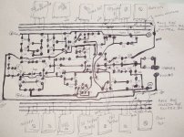
The sequence of images, will show the easy method to produce boards at home, a craftsman style, with a pen painting the board.
I know now a days people loves to produce professional style..but DIY means another different thing, and some guys in this forum are really good ones to produce boards at home.
Final work will show how these modules connect one each other..using wires... to be assembled above a flat heatsink, or a flat surface of a multi finned heatsink.
regards,
Carlos
The first one, i will present now, have the differential and the voltage amplifier...next module will have the VBE multiplier and last module will be the output...i will try to arrange CCS assembled in a pile style, one transistor above the other.
The sequence of images, will show the easy method to produce boards at home, a craftsman style, with a pen painting the board.
I know now a days people loves to produce professional style..but DIY means another different thing, and some guys in this forum are really good ones to produce boards at home.
Final work will show how these modules connect one each other..using wires... to be assembled above a flat heatsink, or a flat surface of a multi finned heatsink.
regards,
Carlos
Attachments

Observing the schematic, watching it and at same time looking at these images
in the sequence, you will perceive this is the schematic...exactly the schematic in positions..what is left in schematic is left here..what is top is top here..what is low position will be low position too....no secret, no trick and no magic..just the most simple possible thing.
Observing you will notice the method is very easy, and that takes much less time than produce boards using software.
It is less pretty, but has more pleasure..as you did..not the software.
This last image..i have just started to join lines in big islands of copper..only the top was made to present the old style to the ones does not know..but the invitation to you, to do it by yourself, producing these "islands" the way you like is registered here.
regards,
Carlos
Attachments
Carlos, my friend. thought you did not like CCS's ??? I was doing this 6 months ago ... http://www.diyaudio.com/forums/solid-state/149324-self-type-3-ef-hybrid-triple-any-pointers.html ,at least to the driver / output stages.
You must of read it , your looks identical.
The real research was already done. A more simple , refined way to do this is run the LPT/VAS from separate PS instead of ALL them CCS's.
On the bright side , at least your horizons have expanded . You now do self amps , combo dx/self amps (bootstrap self amps) , and this one. Ahhh , next you need to do symmetrical or complimentary topo's to complete the "DX" lineup.
Just for understanding , you do not need to use a OP device in the big CCS's (mjl1302) , all the "big ccs" does is "suck out" the carrier charge from all the outputs bases (reduces Xover distortion). Most of the current to push the outputs into conduction is passed through the drivers (mje15032/33) , should use another set of OP's as drivers. Mine (link above)works from 1 pair to 12 pair outputs.
OS
I was doing this 6 months ago ... http://www.diyaudio.com/forums/solid-state/149324-self-type-3-ef-hybrid-triple-any-pointers.html ,at least to the driver / output stages.You must of read it , your looks identical.
The real research was already done. A more simple , refined way to do this is run the LPT/VAS from separate PS instead of ALL them CCS's.
On the bright side , at least your horizons have expanded
. You now do self amps , combo dx/self amps (bootstrap self amps) , and this one. Ahhh , next you need to do symmetrical or complimentary topo's to complete the "DX" lineup.Just for understanding , you do not need to use a OP device in the big CCS's (mjl1302) , all the "big ccs" does is "suck out" the carrier charge from all the outputs bases (reduces Xover distortion). Most of the current to push the outputs into conduction is passed through the drivers (mje15032/33) , should use another set of OP's as drivers. Mine (link above)works from 1 pair to 12 pair outputs.
OS
Last edited:
I still dislike CCS, you see that i am using bootstrapp to VAS in the Blame
This one was made not to my ears...made because a friend that believe CCS is good..so..now he has all the CCS he wants.
I am ready to give to people what they want, despite my personal taste.
The search of inconsistencies in things i do or i say seem unfriendly, also this concern is too small for a man like you..someone who has enjoyed my amplifiers and for sure does not want to spit in the dish you have eated..... if people prefere to look for logical flaws in my person will find a lot of these things..for sure they will... this is very easy to find ... flaws in my amplifiers are also easy to find.....not so easy is to perceive flaws in the sonics..the ones i indicate as good. usually people enjoy.... have built Symassym?..it is also good.
I will not discuss theories.... a never ending thing..build, listen and conclude by yourself.. and this is what you use to do..continue in that direction that is producing to you enormous know how..and read this thread please...you will read, as i said, several times
- " The Troyan sonics is not so good as the Dx Blame sonics."
I have not copied your amplifier..as you use to do things alike i do..we both have the same reference..Doctor Self...i use to copy Doctor Self..maybe our amplifier may be alike..because we have copied (or inspired) from the same source.
Interesting that is so easy to perceive in people's behavior and actions..the limits, the border line in between love and hate is a very thin line.... Siegmund Freud have studied that deeply...people loves me because my amplifiers, also they hate me because of the same amplifiers.
I am ready to give attention when the people is emerged into the love season.
ahahahahahah!
regards,
Carlos
Last edited:
I will not discuss theories
Hey , these are just amplifiers... calm down
I just don't want anybody to get hurt

I will not discuss theories , I will show you.
In the 2 attached pictures , A - B - C are the currents. A is the driver CCS . At 26ma, a mje340 or mje15032 is just fine since the current is constant within a few Ma of 26.
B is the big driver current running the 6 pair of outputs or more into a short
or a bunch of paralleled speakers. At 400 - 800 ma ,you might want to use a output (njw0281)as a driver as a mje15032/33 are too "wimpy" (soa to small) to run all those outputs.C - the most important thing- the load on the vas by the drivers. At 3ma , or even 1ma this will DISTORT the clean music signal produced by the amp in question. This is why an additional pair of predrivers (mje340/350) is used to reduce the load to VAS to microamps. with 3-4 pair output a single pair of mje15033/32 is fine. 5 or more with heavy load , what you see below is the way.
OS
Attachments
Last edited:
- Status
- Not open for further replies.
- Home
- Amplifiers
- Solid State
- Dx Troyan, a 650 watts channel amplifier.