Do you think the V/I limiter is reasonable?
It is working and limiting....i could not find failures till this moment....do you have suggestion to make it better?
You see, in the layout, there are room to install some more parts if needed...maybe to connect the positive rail limiter together the negative rail someway.....you know...i have never used....i made that because Sakis loves that...i dislike...but i have made because of him..... in the reality, as i have never made that, i am no good making that.... i do not know how to make it better...i have readed several books but i could not perceive, clearly, the advantages of one compared to the other.
So.... i have two possibilities, to try all them to evaluate by myself of ask forum folks help.
Can you help please AndrewT?
regards,
Carlos
Last edited:
[snip]The VBE multiplier need some tweak to impeach folks to misadjust into dangerous values of current... this way they cannot make hard mistakes..the trimpot in both extremes of resistance will not be harmfull to the amplifiers.[snip]
Carlos
Carlos,
Just some more free advice: If the bias Vbe pot loses contact with the wiper the bias will skyrocket and the amp will blow up.
If you put the pot in the B-C position, then when the wiper loses good contact, the amp will not blow up but go to zero bias.
jd
I see Janneman, this is a good advice..... i will think about
and will let some time pass till i will tweak once again...Alex mm just made a modification today...will find more things needed and near future i will make some modifications.
First, in advance, i will try another resistance in parallel with the trimpot, not to have all that overcurrent with failures in the trimpot...or will use your suggestion and change the control to the colector... will see that...you know..the tradition to have always in this same position...maybe a PNP transistor...will think about.
Thank you, suggestion is very good...also temperature compensation resistance may be used...will see if there's room in the pcboard layout.
We have time..... only few guys will assemble this amplifier...too much expensive and big...so, we have no hurry till people start to build...they will do it when thread became peacefull and all bugs was found.... when the first one assemble...then others will come, as usuall.
Well boys.... Alexandru had fixed the layout...soon we will have more images, the ones needed to etching boards.
The layout is too much big to publish...so...i gonna do a low resolution pdf. for a while you have this image to take a look if you wish.
Several brazilians are reading, there are many powerholics interested.
regards,
Carlos
Attachments
Last edited:
..... I do not think that's so ....")
Hi Alex,
Edit: Alex, yes you are right, I was mistaken. The way the pot is put is correct.
jd
Last edited:
V/I limiter
Carlos,
Not to split hairs, but the protection system is not really a V/I limiter, it's just an I-limiter. To be a V/I limiter, the protection should react to a carefully set up combination of I (from the Re's) and the Vce (which is the difference between Vout and Vsupply).
R31 seems to do some V-input but is way too high to have any impact.
A V/I limiter is usually dimensioned to provide some SOA-modeling for protection. Often you will see instead of R31 a combination of resistors and zenerdiodes to provide some modelling of the SOA 'breaks' in the SOA curves.
There was a good article about that in Electronics World some years ago from Mikeks (who was a member here), I'll see if I can find it.
jd
Yes, it is more safe..but really..... it is not usuall to have problems with trimpots
As this amplifier manage high power supply, your concerns are very appreciated related to this trimpot...open base there may be a "hell on earth" to the power output transistors....all supply power will go there...not very good, in special positive rail.
Will think about and will return in a couple of days...i am having some occupation in the Brazilian forum too...so.... a little bit busy..but i will manage to study this, and will make it if Alexmm agreed too...we're a team!
regards,
Carlos
some said that the design and some components are not suitable to the power output/psu stated,...that they will not be able to stand 100v of power supply for a long time...
for safety,
i will reduce voltage to be use in the design...i will not go further than 80vdc...
since the only trafo i have is a 55 0 55vac...
i guess somehow this will reduce the risk of for the amp and me as the builder...
still i am open for any suggestions regarding the design that will make it much better than what it is now...
this wont be an easy build for me, i cannot assure to make it right away, for finance is one that makes the project go slow...
tnx,
salamat mga kaibigan
ees...
55-0-55vAC will give you 77-0-77VDC (mine is exactly that) , if it is a 1KVA or better trafo it will blow a screwdriver into balls of molten slag.
As far as suggestions , the resources are available to do it right. ESP project #117 Project 117 is a good example.
Just curious, are you going to power just a bass driver with this insane power ?? If you are, build the triple with 470pF bypasses and the voltage amp with a 150-220pF miller(CDOM). For low frequencies stability is paramount , speed and low distortion are secondary considerations.
OS
As this amplifier manage high power supply, your concerns are very appreciated related to this trimpot.
Will think about and will return in a couple of days...i am having some occupation in the Brazilian forum too...so.... a little bit busy..but i will manage to study this, and will make it if Alexmm agreed too...we're a team!
regards,
Carlos
Carlos, as I answered to Alex, I was mistaken. Forget my comment to the pot.
jd
Well...it is all rigth..if you have a circuit, them please post it here
The V/I limiter..some improved version...but watch the layout..we have not too much room to use too many parts...if your limiter is complex, i will not be able to use as this gonna represent to make the entire layout once again.
I perceive you positive, not destructive, reason why i am reading with attention your posts Janneman... i cannot guarantee i gonna use your schematic, depends on the room into the board and the tests i gonna make with it included in my prototype.... if using transistor, resistance and capacitors only, not beeing complex using Op amps or so on, then i may try it..... Mikeks was addicted to over complicated things...i am not...this amplifier i made is already super crowdy...i do not want to make it more that it already is..because this scares people to build....and if they do not build i will be wasting my time.
I have asked AndrewT too, but as you see...he do not use to help, he only point errors....Old Ostry became destructive, he wants me to stop and build ESP....no fun to copy ESP amplifiers, this one i have created from the scratch, calculated and built...much more fun.... a really mine amplifier.
regards,
Carlos
Last edited:
Carlos, as I answered to Alex, I was mistaken. Forget my comment to the pot.
jd
Great , Jan , i did lost confidence in my understanding
of the english for a few posts.
it seems that team work will pay after all ....
thats the spirit !!!! a bit here and a bit there and perfect is just arround the corner ...
It seems that no matter what said and by whom and how the point remains the same ...
Uncle Charly is always open to sugestions while continously working for better amps
respect Uncle Charly this the minimoum i can say to forum members like you .
The V/I limiter..some improved version...but watch the layout..we have not too much room to use too many parts...if your limiter is complex, i will not be able to use as this gonna represent to make the entire layout once again.
I perceive you positive, not destructive, reason why i am reading with attention your posts Janneman... i cannot guarantee i gonna use your schematic, depends on the room into the board and the tests i gonna make with it included in my prototype.... if using transistor, resistance and capacitors only, not beeing complex using Op amps or so on, then i may try it..... Mikeks was addicted to over complicated things...i am not...this amplifier i made is already super crowdy...i do not want to make it more that it already is..because this scares people to build....and if they do not build i will be wasting my time.
I have asked AndrewT too, but as you see...he do not use to help, he only point errors....Old Ostry became destructive, he wants me to stop and build ESP....no fun to copy ESP amplifiers, this one i have created from the scratch, calculated and built...much more fun.... a really mine amplifier.
regards,
Carlos
Carlos,
I've no intention and time to custom design a V/I limiter as I am very busy with what will become clear the coming weeks
I only wanted to make clear that the amp has no V/I limiter and what a V/I limiter actually is.
Now that you have lowered the supply and went to 10 pairs my feeling is that the amp is robust enough but if I have some time the coming days I'll run it through my SOA spreadsheet.
jd
I see.... i felt confused too about the VBE multiplier.
well, these last years i became a little bit older.... i felt confused many times... reason why i use to test thing to be sure...i use to make mistakes, to fail alike all humans fail.
I see...it is a current limiter...that limits the power as consequence...as i said, i do not use to build amplifier using limiters...was because old Greek friend Sakis....thank you Sakis..... i have not empathy with limiters, but i can understand it may be needed to high power amplifiers to reduce the quantity of output pairs, and to make them more reliable to heavy duty.
Well, the ones does not need, can just cut it out from the circuit...others can keep the circuit there.
Alike you i am busy...preparing myself to operation visiting Psychologist and Nutrition experts, finishing some exams and taking care of family and also running a thread in the Brazilian forum where some beginners are building the Dx Blame ST...busy is the correct word...but the Troyan is in my bench, i am tweaking from time to time...loading, watching in the scope, replacing some parts, observing the new adjustment to the limiter....really taking care of my baby.
Cold here fellows, a hell cold for us....i am in the Northeast and the temperature here is almost stable in 29 degrées celsius along the whole year..... this winter (here) the temperature dropped to 22 degrees celsius.... and raining, high humidity, it is a hell unconfortable too...i am afraid to get a cold while working, i have to keep windows opened, i am having wind, the window must be opened because solder flux gazes..... i am afraid to get a cold that will impeach me to be submited to a surgery..i am 4 monthes preparing to that....12 pounds loss and hundreds of exams made... i cannot loose my place in the long strip of several chubby to be operated....i am also scared, afraid of the operation..will face..but with my bones shacking...some guys die during the procedure.
But slowly i will be tweaking...if someone decide to build, the amplifier is working, maybe a resistance value will be changed, or i may add two more transistors and a couple of parts to the I limiter.....maybe a zener...i do not know exactly what i gonna do, as i decide this working with the amplifier, measuring and listening.
Visit please my fish.... it is giving me some help...... click the link in the signature folks!
regards,
Carlos
Last edited:

55-0-55vAC will give you 77-0-77VDC (mine is exactly that) , if it is a 1KVA or better trafo it will blow a screwdriver into balls of molten slag.
Just curious, are you going to power just a bass driver with this insane power ?? If you are, build the triple with 470pF bypasses and the voltage amp with a 150-220pF miller(CDOM). For low frequencies stability is paramount , speed and low distortion are secondary considerations.
OS
yes i want to use 55 o 55vac trafo for about 25amperes... if im not wrong, that would be 2.5kva or more...correct me if im wrong...
this huge power would be more suitable for bass operation...
salamat sir,
ees...
custom trafo, and very expencive
well, maybe not so much where you live
such large trafo may be problematic
in terms of both quality and handling
Maybe better to build balanced with lower voltage
and seperate double power supply using 2x 1000watt trafos, each mono amp
stereo box with two big heatsink fore each mono amp would be a natural choise
custom trafo, and very expencive
i save much than buying ready made trafo from a store...
950 watts each channel is the maximum consumption
to each channel, when the amplifier is supplied with 80 volts positive and negative, full power over 4 ohms loads, sinusoidal test signal, from 5 Hertz to 20 kilohertz, unclipped continuous test tone.
Better to use two 1 Kilowatt transformer than to use a single 2 or 2.5 kilowatt transformer.
- Filters to 4 ohms should be 30 thousand microfarads / 100 volts condenser to each rail, for optimum performance..... and to each channel
- Filters to 8 ohms should be 15 thousand microfarads/100 ohms condensers to each rail, for optimum performance... and to each channel.
Using less filtering than that will have the risk to listen the mains frequency tone together the audio signal, this appear clearly into low frequency tones that became changed in pitch ...... not a clean tone is reproduced when you use the power amplifier maximum power.
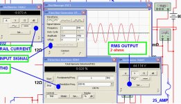
The unclipped output power, near the threshold of clipping will be 680 watts RMS over 4 ohms loads (52 volts RMS)..the current consumption to positive and negative rail will be 5.9 amperes to each rail.... each power transistor will face 590 miliamperes and will be dissipating 47.2 watts.
THD will be 0.01% with 8 ohms speakers, off set will be smaller than 5 milivolts, the input impedance bigger than 45K and sensitivity is 1 volt Peak to maximum output swing.
THD will be 0.008% with 8 ohms speakers, the current to 8 ohms loads will be sligthly higher than 3 amperes to each rail, the ouput RMS voltage will be 53 volts RMS, and this means, as you know, 351 watts RMS to each channel.
In both cases, 8 ohms and 4 ohms, the power transistors will be operating in a safe sittuation...below the maximum rating, and may have long life.
This amplifier does not sound outstanding, the audio quality is normal, it is an average performer, the main characteristic is to produce huge bass, undistorted bass.... despite beeing a full range, a flat amplifier, it is clear its sonic signature that shows a "preference" on the deep bass tones.
Power consumption to 8 ohms is 500 watts to each channel, so, a kilowatt transformer may feed both channels if you decide to operate 8 ohms only.
For a while, the limiter is not entering in action, i will adjust it near the clipping, this will reduce dinamic and peak power, but will prevent distortion.
This is not an amplifier made in the simulator...it was build after calculated, it was built several monthes ago, it played for more than 200 hours...i was using a 100 volts supply that had voltage drop to 80 volts each rail....in my prototype, only 6 power transistors was used and they have survived....so...this amplifier using 10 output pairs will be something to trust, able to face torture and survive.
It will constitute a 1.3 Kilowatt stereo amplifier, reliable, and able to face torture and endurance testing... depending of course the cooling your provide, the heatsink dimension and your output cable quality.... say...normal inductances and capacitances...too many speakers associated use to be a very difficult load i am unable to test...but the amplifier survived to 2 uF in parallel to the output load...the scope had shown normal behavior, the same i found in several other amplifiers.
regards,
Carlos
to each channel, when the amplifier is supplied with 80 volts positive and negative, full power over 4 ohms loads, sinusoidal test signal, from 5 Hertz to 20 kilohertz, unclipped continuous test tone.
Better to use two 1 Kilowatt transformer than to use a single 2 or 2.5 kilowatt transformer.
- Filters to 4 ohms should be 30 thousand microfarads / 100 volts condenser to each rail, for optimum performance..... and to each channel
- Filters to 8 ohms should be 15 thousand microfarads/100 ohms condensers to each rail, for optimum performance... and to each channel.
Using less filtering than that will have the risk to listen the mains frequency tone together the audio signal, this appear clearly into low frequency tones that became changed in pitch ...... not a clean tone is reproduced when you use the power amplifier maximum power.
The unclipped output power, near the threshold of clipping will be 680 watts RMS over 4 ohms loads (52 volts RMS)..the current consumption to positive and negative rail will be 5.9 amperes to each rail.... each power transistor will face 590 miliamperes and will be dissipating 47.2 watts.
THD will be 0.01% with 8 ohms speakers, off set will be smaller than 5 milivolts, the input impedance bigger than 45K and sensitivity is 1 volt Peak to maximum output swing.
THD will be 0.008% with 8 ohms speakers, the current to 8 ohms loads will be sligthly higher than 3 amperes to each rail, the ouput RMS voltage will be 53 volts RMS, and this means, as you know, 351 watts RMS to each channel.
In both cases, 8 ohms and 4 ohms, the power transistors will be operating in a safe sittuation...below the maximum rating, and may have long life.
This amplifier does not sound outstanding, the audio quality is normal, it is an average performer, the main characteristic is to produce huge bass, undistorted bass.... despite beeing a full range, a flat amplifier, it is clear its sonic signature that shows a "preference" on the deep bass tones.
Power consumption to 8 ohms is 500 watts to each channel, so, a kilowatt transformer may feed both channels if you decide to operate 8 ohms only.
For a while, the limiter is not entering in action, i will adjust it near the clipping, this will reduce dinamic and peak power, but will prevent distortion.
This is not an amplifier made in the simulator...it was build after calculated, it was built several monthes ago, it played for more than 200 hours...i was using a 100 volts supply that had voltage drop to 80 volts each rail....in my prototype, only 6 power transistors was used and they have survived....so...this amplifier using 10 output pairs will be something to trust, able to face torture and survive.
It will constitute a 1.3 Kilowatt stereo amplifier, reliable, and able to face torture and endurance testing... depending of course the cooling your provide, the heatsink dimension and your output cable quality.... say...normal inductances and capacitances...too many speakers associated use to be a very difficult load i am unable to test...but the amplifier survived to 2 uF in parallel to the output load...the scope had shown normal behavior, the same i found in several other amplifiers.
regards,
Carlos
Last edited:
I cannot test real life with 2 ohms...i have not enough power in my supplies
to do this job..also i have no enough filters.
But, at least in the simulator it can reach almost a kilowatt of power.... transistors, i believe, may survive.....but i am not sure because i cannot test....maybe the use of some more pairs will make it "hard to kill"...maybe 4 or 5 pairs more..then you will have a nice 2 kilowatt amplifier, able to face 2 ohms.
The CCS to the driver is doing that job, we're having enougth current delivered to the output to face low impedance loads, also the multiple output pairs and the current applied to the VAS.
I am not suggesting dear friends to use it with 2 ohms...but it is relaxing to know it can face some speakers that have strange impedance in some frequency... may face difficult loads and some crazy reactive crossovers.
Reserve of reliability with 4 ohms... this may be the point.
I use to listen it here.... furniture and windows goes shacking...huge power that saturates my year....i just cannot listen it full power for more than half second.. i feel pain in my ears..... it is not awsome in sonics,not special, has not special points...a very standard, normal, common, sound amplifier...alike hundreds of others...but seems it is huge and reliable, and the strength in the bass is impressive.
I mean,...there's no magic on it... this one is just a huge power amplifier, without losses, give us the emotion of the life performance loudness... the vibrations in our body...sounds loud when you go out from your appartment..walls are not a shield to all that power...all shakes....even the concrete pavement shakes...speaker almost jump out from the frame, even my hard to move automobile audio competition speaker.
It will not be beated..but also will not beat others....maybe loudness and power, efficiency maybe...but anything more than that.
I want to make it hundred percent safe...will work for that, the target will be an undestructable unit.... i will check if can face short circuits in the ouput.
Doing this unit i am proving to myself and others interested to study...that sophistication, crowdy circuits, multiple surrounding auxiliary sub circuits alike CCS does not guarantee special sonics... the Dx Blame ST is simple and beat this one easy, laughing, rolling in the floor inserting in an never ending LOL process...laughing till loose the air after fell down from the chair.
regards,
Carlos
Attachments
Last edited:
- Status
- Not open for further replies.
- Home
- Amplifiers
- Solid State
- Dx Troyan, a 650 watts channel amplifier.