Why do people post such silly stuff?
Why do you think that?
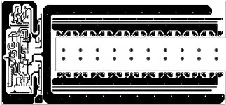
Ok than what do you think about this project. I really want to make this one and it has PCB and everything.
I think it is called AV1000
Attachments
Last edited:
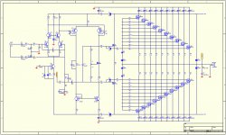
I want to build this amplifier. What do you think is this ok schematic according to you?
Thanks
It looks very crude and simplistic.
There doesnt seem to be a proper bias circuit.
Why do you think that?
Ok than what do you think about this project. I really want to make this one and it has PCB and everything.
I think it is called AV1000
I think sawreyrw might have been responding to post #2..
In any event I can't imagine why you need so much power. It would be safer to build a number of smaller amplifiers to total the required power if you are driving subwoofers or the like. (I don't know of anything that can handle appreciably more than 1kW.)
Can you tell us what this amplifier is to be used for?
I'm a little concerned that the amplifier shown has no overcurrent limiting, thermal protection or otherwise. Power levels like this will require large heatsinks and forced air cooling. Output current at full power would be 65Arms or 92Apk, can't imagine that there is enough copper on those traces to handle that much current.
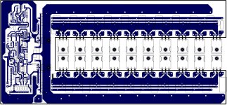
Edit: Actually looking at the second schematic I see it does have a rudimentary form of current limiting, without knowing the Vgs of the devices I cannot determine what the current limit clamps at.. This strikes me as an amp designed for about 1kW output however... (AV1000 a potential clue?)
Truthfully if you do need this kind of power and have AC mains that can provide >40A @ 240V (or >30A 3 phase 380V - 440V) then you might want to look for a surplus "gradient amplifier" - these come in power ratings of 10kW and beyond and will do 20 - 20kHz in a lot of cases at these power levels. Such an amplifier will have thermal and overload protection, and have all requisite safety agency approvals - something you probably want at these power levels. They usually offer internally configurable current or voltage output drive options, may also provide programmable V/I limiting for load protection.
Last edited:
")
Why do you think that?
Ok than what do you think about this project. I really want to make this one and it has PCB and everything.
I think it is called AV1000
Well, for starters your MJE350 is a 300 device you're trying to run at 360 V p-p. The 1/2 watt 3300 ohm resistor will be dissipating 9.8 watts. The 1/2 Watt 1K resistor will be on fire. The power supply...... Whats not silly about all of this?
G²
The speaker symbol is undersized. I'm at a loss for how you could get less than about -5 volts out of the first one (before the flames start), and I guess the body diodes are the output clamps. It also seems to have an inverting output fed back to the inverting input. It's definitely a joke.
Last edited:
I didn't look too closely at the first design, but yes it is an oscillator, and one that will self-destruct rather quickly due to the under-rating of a number of components like the 3.3K resistor. And I've no idea if any of the transistors listed are suitable for the currents or voltages required, and I haven't the time to check.
I think the serious problems will start before you burn out the 3.3k, since the lower FET bank will be hard saturated by the time it gets 12 volts across it.
The source resistor on the upper driver will never allow much more than 0 volts on the drain with 1k on it too, which means the upper bank can't be driven much below that. When the lower bank tries to pull the output any lower, BOOM!
I can't even read the second drawing.
The source resistor on the upper driver will never allow much more than 0 volts on the drain with 1k on it too, which means the upper bank can't be driven much below that. When the lower bank tries to pull the output any lower, BOOM!
I can't even read the second drawing.
Last edited:
Why do you think that?
Ok than what do you think about this project. I really want to make this one and it has PCB and everything.
I think it is called AV1000
Be a kind.., Love yourself, also there are many living things around you. Everything has its responsibility at the last.
Wouldn't even consider the first. The second, at first glance, appears to be better thought out. However, there is still the issue of when you'd ever need this? No single driver can handle anything like that power and if you are using multiple drivers totalling up to that power range, then it really just makes sense to use multiple amplifiers too.
Also, at this sort of power output, class-D makes more sense, and considering the complexity of such a design you'd be best off buying a ready made LabGruppen amplifier like this:
FP 10000Q - Introduction | Lab.gruppen
Much safer and probably cheaper too, IF you truly do need such output (I think those amplifiers are designed to power whole line arrays or banks of subwoofers for live sound reinforcement).
For that application I really do reccomend just buying PA amplifiers, perhaps like the one I linked, but there are many ones around and they are cheap and reliable. I don't know your speaker configuration so can't really say exactly what you need, one mono 7KW amp certainly won't be your best bet though!
how right you are.One smaller amp per driver is a better idea. Then an individual failure doesn't shut you down.
Just imagine the reputation one will have if the system did shut down half way through the night's entertainment.
Bridged mode and low impedance speakers just don't go together!
One smaller amp per driver is a better idea. Then an individual failure doesn't shut you down.
Absolutely agree, this is the way to go. You can even use large stereo amps and drive one woofer per channel. Not a bad idea to locate the amplifiers remotely and near the woofers they are driving to reduce IR losses in the speaker wiring.. Balanced inputs via TRS or XLR are strongly recommended for hum/noise rejection. (Drive should be balanced)
Reliability is paramount so having lots of smaller amplifiers means that if one fails you do not loose all of your bass bins.
Powering smaller amps can be done with conventional 10A or 20A 240V wiring as well.
- Status
- This old topic is closed. If you want to reopen this topic, contact a moderator using the "Report Post" button.
- Home
- Amplifiers
- Solid State
- 7800W at 2ohm. Is this schematic going to work? what do you think.