hello,
the Elektor May 1970 issue is downloadable here : Verstärkermetamorphosen - ELEKTOR.de | Elektronik: Analog Digital Embedded Mikrocontroller Audio Messtechnik
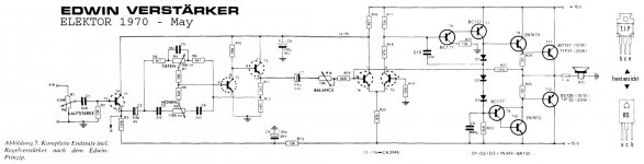
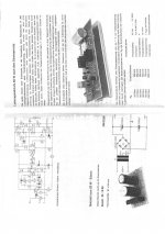
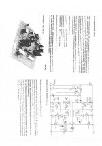
Have a look to the Elektor Edwin 20 watt schematic (attached .jpg). There is a small class A amplifier nested inside a pure (zero bias) class B output stage.
Anybody still owning such amplifier ? What are the subjective results ?
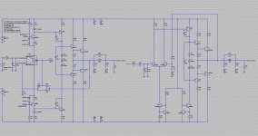
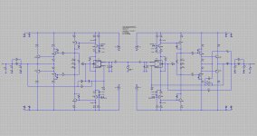
I took some time deriving two modern versions of the Edwin 20 watt amplifier, using LTspiceIV. Version A should be easy to build, no adjustments, and uses an opamp as front-end. Version B is more conventional, with a differential NPN pair at the input, but needs care for getting a low DC offset at the output.
Performance looks decent on simulation.
During the simulation sessions, I have noticed unstabilities when using BD237/DB238 transistors in the VAS. I then realized it would be needed to have specific transistors in the VAS, instead of using the same as in the small class A. I have tried BF469/BF470 transistors, but still getting HF oscillations. The best stability came with 2N5550/2N5401 transistors in the VAS. I have the impression that Edwin is hard to stabilize because there is a steep open loop gain jump each time the class B gets activated. When testing the amplifier on simulation, it is essential to verify the voltage and current waveforms in the VAS, at different power levels like 1mV input, 10 mV input, 100 mV input and 1000 mV input. The compensation caps are mandatory. If you halve their values, you'll experince HF oscillations bursts at high power.
Cheers,
Steph
the Elektor May 1970 issue is downloadable here : Verstärkermetamorphosen - ELEKTOR.de | Elektronik: Analog Digital Embedded Mikrocontroller Audio Messtechnik
Have a look to the Elektor Edwin 20 watt schematic (attached .jpg). There is a small class A amplifier nested inside a pure (zero bias) class B output stage.
Anybody still owning such amplifier ? What are the subjective results ?
I took some time deriving two modern versions of the Edwin 20 watt amplifier, using LTspiceIV. Version A should be easy to build, no adjustments, and uses an opamp as front-end. Version B is more conventional, with a differential NPN pair at the input, but needs care for getting a low DC offset at the output.
Performance looks decent on simulation.
During the simulation sessions, I have noticed unstabilities when using BD237/DB238 transistors in the VAS. I then realized it would be needed to have specific transistors in the VAS, instead of using the same as in the small class A. I have tried BF469/BF470 transistors, but still getting HF oscillations. The best stability came with 2N5550/2N5401 transistors in the VAS. I have the impression that Edwin is hard to stabilize because there is a steep open loop gain jump each time the class B gets activated. When testing the amplifier on simulation, it is essential to verify the voltage and current waveforms in the VAS, at different power levels like 1mV input, 10 mV input, 100 mV input and 1000 mV input. The compensation caps are mandatory. If you halve their values, you'll experince HF oscillations bursts at high power.
Cheers,
Steph
Attachments
In the seventies, semiconductor designers were pretty bold and confident; one might even say "gung ho".
They thought they could get away with unbiased output transistors.
The thing was in the air, and there are numerous examples dating from that era.
At the time, Hermann Schreiber was a contributor to the French magazine "Le Haut-Parleur", and he described a number of such circuits (BTW, H Schreiber was also an excellent author and electronician).
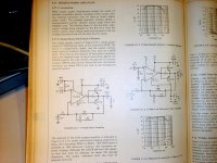
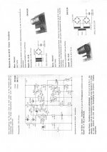
IC manufacturers also proposed this kind of circuit to boost the output of small amplifiers. Here is an example from National.
The belief behind those circuit was that no crossover distortion could appear, because the output was always connected to the signal, and the transition between the two modes was supposed to be smooth.
The cold truth is that the scheme is worthless, and they sound awful, even though figures can look decent.
They thought they could get away with unbiased output transistors.
The thing was in the air, and there are numerous examples dating from that era.
At the time, Hermann Schreiber was a contributor to the French magazine "Le Haut-Parleur", and he described a number of such circuits (BTW, H Schreiber was also an excellent author and electronician).
IC manufacturers also proposed this kind of circuit to boost the output of small amplifiers. Here is an example from National.
The belief behind those circuit was that no crossover distortion could appear, because the output was always connected to the signal, and the transition between the two modes was supposed to be smooth.
The cold truth is that the scheme is worthless, and they sound awful, even though figures can look decent.
Attachments
Some guys claim, that this circuit was a simplefield circuit of the current dumping amp Quad 405
http://www.fralu.de/images/qaud405.jpg
But the only identical thing that I know is the no needed idle current adjust.
BTW this amp was my first amplifier project (arround 1976). It was a amp kit from Oppermann electronic include PCB.
http://www.fralu.de/images/qaud405.jpg
But the only identical thing that I know is the no needed idle current adjust.
BTW this amp was my first amplifier project (arround 1976). It was a amp kit from Oppermann electronic include PCB.
Actually Quad 'current dumping' is a misnomer. Peter Walker patented it with it's proper name, which is a form of feedforward. As a result, many amplifiers that connect B-E of the output transistors across a resistor in series between the previous stage and load, were called 'current dumping'. Ironically, it is a fitting name for those, while they have nothing in common with the Quad topology.
That's not quite possible because Edwin got presented in Elektor in May 1970, and the Quad 405 got presented by P.J. Walker and M.P. Albinson at the AES in 1975. A possibility is that Walker or Albinson creative imagination got triggered upon discovering the Edwin amplifier in Elektor. Have you noticed, in the Quad 405, the integrated circuit used as preamp ? That's another diffuse similitude with Edwin ...Some guys claim, that this circuit was a simplifield circuit of the current dumping amp Quad 405.
In the Edwin circuit, there is no idle current in the output trannies, they are in class C. They draw current only when there is sufficient voltage across the driver resistors to bias them.
The same idea was used in Phase Linear and ESS big power amps, and probably some others, and more recently, by Graham Nalty in his Apex amplifier described in ETI.
The same idea was used in Phase Linear and ESS big power amps, and probably some others, and more recently, by Graham Nalty in his Apex amplifier described in ETI.
QUOTE=tiefbassuebertr BTW this amp was my first amplifier project (arround 1976). It was a amp kit from Oppermann electronic include PCB
hello.
found something.........
hello.
found something.........
Attachments
Last edited:

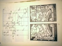
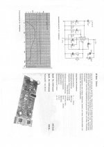
here you will discover how an Edwin can become a Quad 405, same PCB, same output devices, only a few localized differences.
High-power distorsion :
*****************
Fourier components of V(edwin)
DC component:-0.00070647
Harmonic Frequency Fourier Normalized Phase Normalized
Number [Hz] Component Component [degree] Phase [deg]
1 1.000e+03 2.252e+01 1.000e+00 -0.22° 0.00°
2 2.000e+03 3.725e-05 1.654e-06 2.06° 2.28°
3 3.000e+03 2.567e-05 1.140e-06 -82.88° -82.67°
4 4.000e+03 2.173e-06 9.649e-08 -61.81° -61.59°
5 5.000e+03 5.246e-05 2.330e-06 -86.07° -85.86°
6 6.000e+03 1.753e-06 7.785e-08 -40.68° -40.47°
7 7.000e+03 4.834e-05 2.147e-06 -84.56° -84.35°
8 8.000e+03 8.157e-07 3.622e-08 -29.85° -29.63°
9 9.000e+03 4.766e-05 2.117e-06 -84.18° -83.96°
Total Harmonic Distortion: 0.000431%
Fourier components of V(quad405)
DC component:-0.000729602
Harmonic Frequency Fourier Normalized Phase Normalized
Number [Hz] Component Component [degree] Phase [deg]
1 1.000e+03 2.323e+01 1.000e+00 -0.27° 0.00°
2 2.000e+03 4.585e-05 1.974e-06 4.51° 4.79°
3 3.000e+03 8.381e-06 3.608e-07 14.11° 14.39°
4 4.000e+03 1.684e-06 7.251e-08 -56.56° -56.29°
5 5.000e+03 3.481e-05 1.499e-06 -79.20° -78.93°
6 6.000e+03 1.862e-06 8.017e-08 -31.06° -30.79°
7 7.000e+03 3.070e-05 1.322e-06 -77.28° -77.01°
8 8.000e+03 9.427e-07 4.059e-08 -25.73° -25.46°
9 9.000e+03 3.110e-05 1.339e-06 -77.89° -77.62°
Total Harmonic Distortion: 0.000313%
Low-power distorsion :
*****************
Fourier components of V(edwin)
DC component:-0.000698215
Harmonic Frequency Fourier Normalized Phase Normalized
Number [Hz] Component Component [degree] Phase [deg]
1 1.000e+03 2.252e+00 1.000e+00 -0.22° 0.00°
2 2.000e+03 1.350e-06 5.996e-07 -9.77° -9.55°
3 3.000e+03 4.080e-05 1.812e-05 -90.40° -90.18°
4 4.000e+03 3.852e-07 1.711e-07 -23.20° -22.98°
5 5.000e+03 3.719e-05 1.652e-05 -89.95° -89.73°
6 6.000e+03 1.327e-07 5.891e-08 -56.46° -56.25°
7 7.000e+03 3.455e-05 1.534e-05 -89.54° -89.32°
8 8.000e+03 1.458e-07 6.475e-08 -141.97° -141.76°
9 9.000e+03 3.239e-05 1.438e-05 -89.17° -88.95°
Total Harmonic Distortion: 0.003231%
Fourier components of V(quad405)
DC component:-0.0007204
Harmonic Frequency Fourier Normalized Phase Normalized
Number [Hz] Component Component [degree] Phase [deg]
1 1.000e+03 2.323e+00 1.000e+00 -0.27° 0.00°
2 2.000e+03 1.249e-06 5.378e-07 -5.24° -4.97°
3 3.000e+03 2.823e-05 1.215e-05 -82.00° -81.72°
4 4.000e+03 3.808e-07 1.639e-07 -18.17° -17.90°
5 5.000e+03 2.689e-05 1.158e-05 -84.54° -84.26°
6 6.000e+03 2.349e-07 1.011e-07 -29.63° -29.36°
7 7.000e+03 2.594e-05 1.117e-05 -85.41° -85.14°
8 8.000e+03 1.630e-07 7.017e-08 -47.12° -46.84°
9 9.000e+03 2.514e-05 1.083e-05 -85.76° -85.48°
Total Harmonic Distortion: 0.002289%
See the attached .zip containing everything for LTspiceIV.
Cheers,
Steph
Attachments
Last edited:
QUOTE=tiefbassuebertr BTW this amp was my first amplifier project (arround 1976). It was a amp kit from Oppermann electronic include PCB
hello.
found something.........
Exactly - the 20W EDWIN
Unfortunately it was stolen from me during the time in the military (the closed locker, where the amp was stored at the weekend, was screwed from behind). So I cannot make a soundcheck and comparable test with today's amp projects
Apexaudio: this is a normal Class AB amp; R9 can replace with a variable resistor.
Curious is the not presently emitter resistor, so that the cross current through T1 was only the base input current of T2 (only uA aera - hugh design failure and main reason for bad sound !!!).
Last edited:
Exactly - the 20W EDWIN
Unfortunately it was stolen from me during the time in the military (the closed locker, where the amp was stored at the weekend, was screwed from behind). So I cannot make a soundcheck and comparable test with today's amp projects
.
Not a big loss, anyway...
This elektor amp is a complete failure on its own.
Fortunately, they much improved their designs the
following years..
I have 'Equa' in JPG format, but not on English (Serbian)Very interesting to look at those old designs. Anyone got a copy of the Elektor 'Equa' amplifier. I looked on the web - no luck. Its from about 1975 or 1976.
thanks
")
Not a big loss, anyway...
This elektor amp is a complete failure on its own.
Fortunately, they much improved their designs the
following years..
Indeed.
This kind of amplifier is basically a square wheel made to (sort of) work.
But when you look into the details, you understand immediately they're hopelessly flawed.
Here is the residue appearing between the inputs of the diff amp:
It says more than a thousand words.
Attachments
Hello, it is not a flaw, it is a feature ! By the way, I am now including the test you've done (voltage on the diff amp), as routine health check. Thanks ! I agree with you that if music is supposed to be delivered by such an amplifier, the tiny variations around the zero may be ignored, masked, erased while the amp is so heavily busy, eliminating the crossover distorsion. Kind of window opening and closing at each crossing. One may learn something, listening to such "flawed" amp ... Don't you think ?Indeed. This kind of amplifier is basically a square wheel made to (sort of) work. But when you look into the details, you understand immediately they're hopelessly flawed. Here is the residue appearing between the inputs of the diff amp (see waveform previous post): it says more than a thousand words.
Hello, it is not a flaw, it is a feature ! One may learn something, listening to such "flawed" amp ..
A feature ?...Perhaps for a guitar amp overdrive function...
Attachments
From the view of the real value here of course not, but from the view of the sentimental value, since even a lot of work has been invested for the enclosure resp. cabinet (also a FM Stereo Kit (FD1A/uA703/CA3189/MC1310P) was integrated).wahab;2156394 from post #12 said:Not a big loss, anyway...
This elektor amp is a complete failure on its own.
Fortunately, they much improved their designs the
following years..
Bonsai post #13:
Very interesting to look at those old designs. Anyone got a copy of the Elektor 'Equa' amplifier. I looked on the web - no luck. Its from about 1975 or 1976.
From this amp I have win an auction from the concerning elektor magazine last year. I have build this amp, but I get an oscillator. The reason is the topology of the output stage. Also in the Pspice simulaion I observe the same oscillation effect
The output stage should be an improved topology (with respect to the symmetry between the positive and half negative half) compared with those from the Quad 303.
Until this day I haven't found a satisfy solution to remove the reason for the oscillation (except the use of the normal two stage buffer, i. e. darlington for the pos. half and sziklai darlington for the neg. half
- Status
- This old topic is closed. If you want to reopen this topic, contact a moderator using the "Report Post" button.
- Home
- Amplifiers
- Solid State
- Edwin 20 watt (Elektor 1970 - May)