Dear All,
Here a question with examples, that we might can all learn from. There are many good articles, and education about grounding and where to get the star point. However, all those articles refer to a classic two or four capacitor power supply. Some designers and/or DIY-ers choose for designs with multiple smaller capacitors. I would like to keep this point out of the discussion (multiple smaller caps or two big caps enz.) this is pure about grounding. Also don't pay attention to the track size enz. Those drawings are only for animation to get the idea of my question.
The idea is to use multiple cap's on the amplifier board itself, and feed the output devices from here, then ground the de-couple cap's, audio lines etc. from a common star-ground. But then, where to take the star-ground point...?
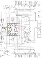
A first example is how Rotel does it's grounding. After owned Rotel Amplifiers, I must say they where always silent, no noise, no hum. See attachment one for example.
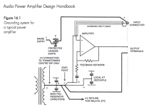
However Self state in his book "The positive and negative rail reservoir caps will be joined together by a thick earth connection; this is called Reservoir Ground (RG). Do not attempt to use any point on this track as the audio-ground star-point, as it carries heavy charging pulses and will induce ripple into the signal. Instead take a thick tee from the centre of this track (through which the charging pulses will not flow) and use the end of this as the starpoint."
But as we can see , Rotel use this RG bridge as star-ground point, and with good results.
Iillustrate some grounding options in eagle, and I would like to hear some suggestions, with pro's and/or con's from each example. For connivence I will call the copper track between the reservoir capacitors "RG" like Self.
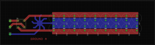
GROUND A
The star-ground point is taken between the bridge-rectifier and the RG. The 0 volt transformer point is taken from the same star-ground point.
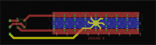
GROUND B
The star-ground point is taken at the middle of the RG. The 0 volt transformer line is taken from this star-ground point as well
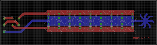
GROUND C
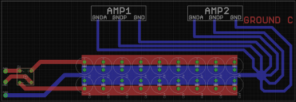
The star-ground point is taken at the end of the power supply after the RG. The transformer 0 volt point is directed at the start between the bridge rectifier and RG.
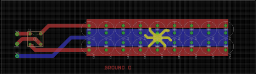
GROUND D
The star point is taken at the middle of the RG, but the transformer 0 volt line is directed between the bridge rectifier and RG
Thank you in advance. I look forward to the response.
With kind regards,
Bas
Here a question with examples, that we might can all learn from. There are many good articles, and education about grounding and where to get the star point. However, all those articles refer to a classic two or four capacitor power supply. Some designers and/or DIY-ers choose for designs with multiple smaller capacitors. I would like to keep this point out of the discussion (multiple smaller caps or two big caps enz.) this is pure about grounding. Also don't pay attention to the track size enz. Those drawings are only for animation to get the idea of my question.
The idea is to use multiple cap's on the amplifier board itself, and feed the output devices from here, then ground the de-couple cap's, audio lines etc. from a common star-ground. But then, where to take the star-ground point...?
A first example is how Rotel does it's grounding. After owned Rotel Amplifiers, I must say they where always silent, no noise, no hum. See attachment one for example.
However Self state in his book "The positive and negative rail reservoir caps will be joined together by a thick earth connection; this is called Reservoir Ground (RG). Do not attempt to use any point on this track as the audio-ground star-point, as it carries heavy charging pulses and will induce ripple into the signal. Instead take a thick tee from the centre of this track (through which the charging pulses will not flow) and use the end of this as the starpoint."
But as we can see , Rotel use this RG bridge as star-ground point, and with good results.
Iillustrate some grounding options in eagle, and I would like to hear some suggestions, with pro's and/or con's from each example. For connivence I will call the copper track between the reservoir capacitors "RG" like Self.
GROUND A
The star-ground point is taken between the bridge-rectifier and the RG. The 0 volt transformer point is taken from the same star-ground point.
GROUND B
The star-ground point is taken at the middle of the RG. The 0 volt transformer line is taken from this star-ground point as well
GROUND C
The star-ground point is taken at the end of the power supply after the RG. The transformer 0 volt point is directed at the start between the bridge rectifier and RG.
GROUND D
The star point is taken at the middle of the RG, but the transformer 0 volt line is directed between the bridge rectifier and RG
Thank you in advance. I look forward to the response.
With kind regards,
Bas
Attachments
Don't use fills, use lines on the board, in order to simply show you where the current loops are, keeping in mind that every line is a resistor (you can disregard the inductive part) - and the point is to keep the rectifier cap charging current and the amp supply current separate. Of course, they overlap, so you can only keep them least overlapped - in other words, look that the currents that must not mix, go through the largest number of 'resistors' to get to each other's loop. This will show you that option C is what you want.
Don't use fills, use lines on the board, in order to simply show you where the current loops are, keeping in mind that every line is a resistor (you can disregard the inductive part) - and the point is to keep the rectifier cap charging current and the amp supply current separate. Of course, they overlap, so you can only keep them least overlapped - in other words, look that the currents that must not mix, go through the largest number of 'resistors' to get to each other's loop. This will show you that option C is what you want.
Dear,
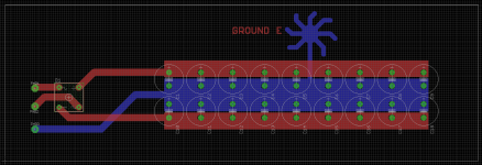
I offer an Option E. let's say the output devices are located above the capacitors. Then it would be more convenient to have the star ground not to far away (routing wise). Will option E be a good idea? Either way with option C or option E, the 0 volt transformer ground must not be connected to the same start-ground but at the left side of the RG?
Thanks in advance for the advice.
With kind regards,
Bas
Attachments
Now that i have thought about this i'd still go for option "C", however, the speaker current in a standard non bridge amplifier would return to the star point.
There might be a possibility that the speaker ground might be better returned to the connection point of the transformer grounds rather than the star point. This would remove any heavy currents from the star point entirely. Can't say i have tried this, it's just a thought that may or may not have some value")
There might be a possibility that the speaker ground might be better returned to the connection point of the transformer grounds rather than the star point. This would remove any heavy currents from the star point entirely. Can't say i have tried this, it's just a thought that may or may not have some value
Thanks again for the responses.
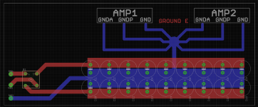
Please allow me to show two more examples. AMP-1 and AMP-2 Are complete amplifier stages, with VAS, outputstage etc, but all on the same PCB. IT is clear that everyone prefers option C (which I was afraid for). But as seen in this illustration, it gives some routing mess. Would option E be a alternative?
With kind regards,
Bas
Attachments


Option "E" is just the same as "C" but with the star in what i would say was a non optimum position. If you look at C & E they are the same, except that instead of it being connected to what would be the very centre of the connections to the +/- of the capacitors forming the ground, it's one sided.
Dump it, keep it as symmetrical as possible imo, though what do i know
I think i'll have to experiment with ground returns, having suggested the speaker ground returning to the same point as the transformer grounds (& i like this idea) to keep any heavy currents from interacting with the star ground.
Cheers for making me think about minutae
Option "E" is just the same as "C" but with the star in what i would say was a non optimum position. If you look at C & E they are the same, except that instead of it being connected to what would be the very centre of the connections to the +/- of the capacitors forming the ground, it's one sided.
Dump it, keep it as symmetrical as possible imo, though what do i know
I think i'll have to experiment with ground returns, having suggested the speaker ground returning to the same point as the transformer grounds (& i like this idea) to keep any heavy currents from interacting with the star ground.
Cheers for making me think about minutae
Thank you. You say "keep it symetrical" even despite the fact that you need long ground tracks in case of C?
With kind regards,
Bas
The ground track from the transformers isn't that long is it. Once it reaches that bank of capacitors it usually morphs into at least an 1/8" of aluminium if the caps happen to have screw terminals
I meant all the ground tracks from the amplifier stages all the way to the right side of the PCB with option C.
With kind regards,
Bas
That's fineI meant all the ground tracks from the amplifier stages all the way to the right side of the PCB with option C.
With kind regards,
Bas
Since you brought it up though i'm wondering if it wouldn't be better to connect the speaker grounds to the same point as the 0V or ground of the transformer/s leaving the low current stuff to the star ground. It means that none of the amplifier output (as in to the speaker) current should have any influence on the star ground at all.
Take this with a pinch of salt, i'm on my third pint of snakebite

Bests to you Bas, regards, Mark.
That's fine
Since you brought it up though i'm wondering if it wouldn't be better to connect the speaker grounds to the same point as the 0V or ground of the transformer/s leaving the low current stuff to the star ground. It means that none of the amplifier output (as in to the speaker) current should have any influence on the star ground at all.
Take this with a pinch of salt, i'm on my third pint of snakebite
Bests to you Bas, regards, Mark.
hahaha Cheers my friend
Since my amplifiers are bridged I don't really need to concern about the speaker return grounds, but you brought up a good issue. Let's see what the others say about it. In the meanwhile (if you don't own this bible yourself ) I will look in Mr. Selfs book, if he write about the loudspeaker return ground.With kind regards,
Bas
Don't use fills, use lines on the board, in order to simply show you where the current loops are
Yep, I agree. I wouldn't go for any of your options so far because you've used big land areas for the connections. How about turning all the paralleled caps into a kind of lumped transmission line? You'll get much better rejection of HF that way, rather than just one big 'capacitor farm' as you've shown so far. Each PCB track has some inductance and some resistance, so in conjunction with a single cap you get a lowpass filter. Then put all those LPFs in series.
Yep, I agree. I wouldn't go for any of your options so far because you've used big land areas for the connections. How about turning all the paralleled caps into a kind of lumped transmission line? You'll get much better rejection of HF that way, rather than just one big 'capacitor farm' as you've shown so far. Each PCB track has some inductance and some resistance, so in conjunction with a single cap you get a lowpass filter. Then put all those LPFs in series.
Huh? I doubt you'd want that...one of the purposes of the capacitors is to provide a low impedance to any high frequency currents that might be present, that provides the smoothest, stiffest power supply. On many occasions I've had to come in and fix issues with analog and digital circuitry where a perfectly good bulk supply capacitors or bypass capcitors were negated by being too far away from where they needed to be, or too much inductance. We aren't trying to match impedances here for signal transmission, we are trying to squash noise. I like heavy copper, wide traces and short runs.
-S
Huh? I doubt you'd want that...one of the purposes of the capacitors is to provide a low impedance to any high frequency currents that might be present, that provides the smoothest, stiffest power supply.
Yes, no disagreement. Where are these 'high frequency currents' coming from? If its an amplifier, the most likely source is the mains supply and bridge rectifiers rather than from the amp circuit itself.
On many occasions I've had to come in and fix issues with analog and digital circuitry where a perfectly good bulk supply capacitors or bypass capcitors were negated by being too far away from where they needed to be, or too much inductance.
Yep, you and me both. But we can't see the load on those PCB plots Bas has shown us, we've only got the power supply.
We aren't trying to match impedances here for signal transmission, we are trying to squash noise.
Precisely. I only mentioned 'lumped transmission line' to convey the notion of having series inductance and parallel capacitance. Its impedance is immaterial.
I like heavy copper, wide traces and short runs.
OK, I prefer a slightly more nuanced approach myself, but each to their own
2oz or 4oz copper though could be a great idea here. Seeing as we can never get zero impedance and zero inductance, I prefer to leverage what impedance we can't get rid of to the best advantage.
Last edited:
Huh? I doubt you'd want that...one of the purposes of the capacitors is to provide a low impedance to any high frequency currents that might be present, that provides the smoothest, stiffest power supply. On many occasions I've had to come in and fix issues with analog and digital circuitry where a perfectly good bulk supply capacitors or bypass capcitors were negated by being too far away from where they needed to be, or too much inductance. We aren't trying to match impedances here for signal transmission, we are trying to squash noise. I like heavy copper, wide traces and short runs.
-S
Dear Scot,
That is why I want this bank of small multiple capacitors as close as possible to the output stages, so the supply lines are very short.
With kind regards,
Bas
Dear,
I believe in a very low impedance power supply, with the best ESR as possible.
I've seen big fills in many commercial amplifiers, including Nelson Pass, and it seems to work very well in practice in an power amplifier.
I still can't decide between option E or option C.
With kind regards
Bas
I believe in a very low impedance power supply, with the best ESR as possible.
I've seen big fills in many commercial amplifiers, including Nelson Pass, and it seems to work very well in practice in an power amplifier.
I still can't decide between option E or option C.
With kind regards
Bas
Attachments
- Status
- This old topic is closed. If you want to reopen this topic, contact a moderator using the "Report Post" button.
- Home
- Amplifiers
- Solid State
- Grounding options with multiple cap's