P3A
Some other measurments 23Hz to 70KHz
volume down 1,7w .
This time with a new probe Sr. AndrewT
Some other measurments 23Hz to 70KHz
volume down 1,7w .
This time with a new probe Sr. AndrewT
Attachments
-
 DSC06858.JPG546.9 KB · Views: 667
 -
 DSC06867.JPG546.5 KB · Views: 135
 -
 DSC06866.JPG545.9 KB · Views: 119
 -
 DSC06865.JPG547.9 KB · Views: 119
 -
 DSC06864.JPG623.8 KB · Views: 105
 -
 DSC06863.JPG547.2 KB · Views: 113
 -
 DSC06862.JPG546.5 KB · Views: 501
 -
 DSC06861.JPG623.7 KB · Views: 541
 -
 DSC06860.JPG548.1 KB · Views: 565
 -
 DSC06859.JPG546.6 KB · Views: 616
Last edited:
the squarewave test should be at a voltage significantly below maximum.
As such the PSU should have virtually no effect on the amplifier's processing of the test signal.
We would expect 100Hz to be near flat and 10Hz to show some significant slope due to bass roll off of the AMPLIFIER.
The scope is set to DC input.
The roll off must be in the amplifier.
As such the PSU should have virtually no effect on the amplifier's processing of the test signal.
We would expect 100Hz to be near flat and 10Hz to show some significant slope due to bass roll off of the AMPLIFIER.
The scope is set to DC input.
The roll off must be in the amplifier.
P3A
Hi dear AndrewT.
In the previous post #369 this amplifier tested at about 21w.
My +/-35v power supply isn't high wattage
Now you have the opinion that a more stress test is useful
I must test power supply's maximum current and then i repeat this test at high volume levels.
It's interesting if we have another test by another builder of this amplifier.
In any case bass of this amplifier is strong and deep
Regards.
the squarewave test should be at a voltage significantly below maximum.
As such the PSU should have virtually no effect on the amplifier's processing of the test signal.
We would expect 100Hz to be near flat and 10Hz to show some significant slope due to bass roll off of the AMPLIFIER.
The scope is set to DC input.
The roll off must be in the amplifier.
Hi dear AndrewT.
In the previous post #369 this amplifier tested at about 21w.
My +/-35v power supply isn't high wattage
Now you have the opinion that a more stress test is useful
I must test power supply's maximum current and then i repeat this test at high volume levels.
It's interesting if we have another test by another builder of this amplifier.
In any case bass of this amplifier is strong and deep
Regards.
Last edited:
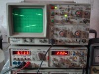
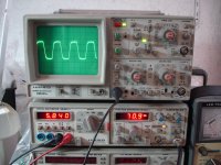
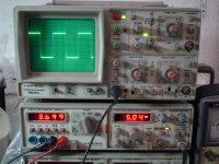
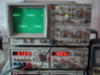
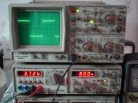
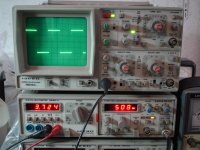
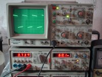
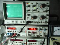
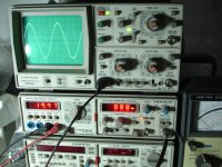
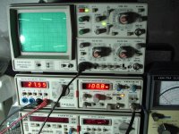
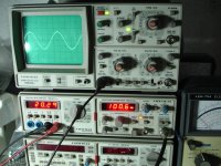
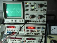
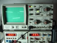
As AndrewT commented, this is low enough power for the amp. to not be affected by a weak power supply.Some other measurments 23Hz to 70KHz
volume down 1,7w .....
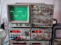
The roll-off seems fairly constant at 6dB/octave above 50 Hz and this suggests an error at the input or VAS stage with the size of the cap. or the PCB routing. It's easy to check initially by increasing the values, even while the amplifier and 'scope are running (at low power and with due care).
Re comparisons with other builders: Sakis already posted 'scope shots of his P3a back at the opening post. In any case, no amplifier should show roll-off at 500 Hz.
Last edited:
Member
Joined 2009
Paid Member
P3A
Thanks all of you for your interesting.
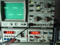
This afternoon i tried to see signal input just after input capacitor with power off.
Note that signal before input capacitor is flat.
Please take a look at these patterns.
Next patterns on volume just before clipping.
Sakis haven't post scopes in low frequencies behind 1KHz.
Thanks all of you for your interesting.
This afternoon i tried to see signal input just after input capacitor with power off.
Note that signal before input capacitor is flat.
Please take a look at these patterns.
Next patterns on volume just before clipping.
Sakis haven't post scopes in low frequencies behind 1KHz.
Attachments
-
 DSC06888.JPG588.1 KB · Views: 86
 -
 DSC06887.JPG586.3 KB · Views: 65
 -
 DSC06886.JPG588.9 KB · Views: 76
 -
 DSC06885.JPG584.3 KB · Views: 77
 -
 DSC06884.JPG574.5 KB · Views: 70
 -
 DSC06883.JPG586.6 KB · Views: 79
 -
 DSC06882.JPG585.8 KB · Views: 90
 -
 DSC06881.JPG603.8 KB · Views: 105
 -
 DSC06880.JPG556.1 KB · Views: 213
Last edited:
Hi thimios,
If you are seeing a roll-off on one side of the input capacitor and not the other, there are two possibilities:
a) The input capacitor is too low in value.
b) There is too much loading on the non-input side of C1, e.g. Resistor R2 is too low in value.
Have you checked these components?
If you are seeing a roll-off on one side of the input capacitor and not the other, there are two possibilities:
a) The input capacitor is too low in value.
b) There is too much loading on the non-input side of C1, e.g. Resistor R2 is too low in value.
Have you checked these components?
You are going to get tired of taking and attaching so many screen shots. You only need 20,50 or 100Hz square waves at most to show the problem, since all the above shots show the same response, apart from slight clipping on #8.
Do both channels have the same reponse?
Have you checked the PCB, components and wiring at the input stage to be certain it is correct?
There are only a limited number of possibilities for this circuit behaviour and magic is not one them, so please take a proper look and compare with the published schematic.
Hi thimios,
If you are seeing a roll-off on one side of the input capacitor and not the other, there are two possibilities:
a) The input capacitor is too low in value.
b) There is too much loading on the non-input side of C1, e.g. Resistor R2 is too low in value.
Have you checked these components?
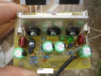
Look this R2.
C1=4u7/63V
I has try to increace but without result.
Attachments
Last edited:
P3A
Pictures in new post are from input.
I have one channel only.
I have check pcb,components and wiring many times.
I don't believe in magic
If you got tired you can stop replying
You are going to get tired of taking and attaching so many screen shots. You only need 20,50 or 100Hz square waves at most to show the problem, since all the above shots show the same response, apart from slight clipping on #8.
Do both channels have the same reponse?
Have you checked the PCB, components and wiring at the input stage to be certain it is correct?
There are only a limited number of possibilities for this circuit behaviour and magic is not one them, so please take a proper look and compare with the published schematic.
Pictures in new post are from input.
I have one channel only.
I have check pcb,components and wiring many times.
I don't believe in magic
If you got tired you can stop replying
Look this R2.
C1=4u7/63V
I has try to increace but without result.
I presume you've thoroughly checked the PCB for errors or shorts...
Does the signal change in shape at the junction of C1/R2 when power is applied to the amplifier (for example with a 60Hz squarewave input)?
Thanks all of you for your interesting.
This afternoon i tried to see signal input just after input capacitor with power off.
Note that signal before input capacitor is flat.
Please take a look at these patterns.
Next patterns on volume just before clipping.
Sakis haven't post scopes in low frequencies behind 1KHz.
It looks ok to me.
No it doesn't.It's the same thing.I presume you've thoroughly checked the PCB for errors or shorts...
Does the signal change in shape at the junction of C1/R2 when power is applied to the amplifier (for example with a 60Hz squarewave input)?
P3A
Hi dear you're right ,just now i see here 2:09.APEX AX11 pushing AX11 at the limits - YouTube
Testing another amplifier Apex ax-11 at frecuency 23Hz same results.
It looks ok to me.
Hi dear you're right ,just now i see here 2:09.APEX AX11 pushing AX11 at the limits - YouTube
Testing another amplifier Apex ax-11 at frecuency 23Hz same results.
Last edited:
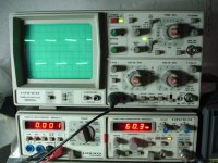
I agreed with AndrewT's analysis of the low-frequency squarewave shape in that the response is rolling-off at low frequencies, seemingly at too high a frequency. However, there is an easy way to identify the -3dB roll-off point to verify if this is normal behaviour:
Using a sine wave input signal at around 2KHz (set the amplitude to well below clipping level), measure the amplifier's output amplitude on your oscilloscope. Then reduce the signal frequency (only) until the output amplitude drops to about 0.71 of it's original value. This will give the -3dB low-frequency point.
Using a sine wave input signal at around 2KHz (set the amplitude to well below clipping level), measure the amplifier's output amplitude on your oscilloscope. Then reduce the signal frequency (only) until the output amplitude drops to about 0.71 of it's original value. This will give the -3dB low-frequency point.
I agreed with AndrewT's analysis of the low-frequency squarewave shape in that the response is rolling-off at low frequencies, seemingly at too high a frequency. However, there is an easy way to identify the -3dB roll-off point to verify if this is normal behaviour:
Using a sine wave input signal at around 2KHz (set the amplitude to well below clipping level), measure the amplifier's output amplitude on your oscilloscope. Then reduce the signal frequency (only) until the output amplitude drops to about 0.71 of it's original value. This will give the -3dB low-frequency point.
Thanks currentflow....you mean the "curve of frequency response" of an amplifier,
For a more accurate measurment you must monitor the input signal too.
Attachments
Last edited:
Member
Joined 2009
Paid Member
As you have such a nice new oscilloscope you might also monitor the phase difference between input and output - usually when there is roll-off due to RC filter you will see the phase shift.
You could also do a 'control' experiment, try the measurement on another amplifier that you know to work to spec. which will rule out a measurement method fault.
You could also do a 'control' experiment, try the measurement on another amplifier that you know to work to spec. which will rule out a measurement method fault.
- Home
- Amplifiers
- Solid State
- P3A Comparison table ( long .... )