There is no optimum value ...up to a point though its only waste of them
I think that amplifier will work happily with anything above 2X4700 per amplifier and i run mine at 30.000 mfd per amplifier
In the boards i make now days i Bypass them with 2.2ufd MKS
As about matching i worked 3 different versions through a period of time
A) i built a board that was made with what ever parts i find in front of me including TIP3055-TIP2955 for outputs and no matching at all measured horrible and sounded bad
B) version that has quality parts but only the LTP matched with the use of a simple hfe instrument that exists in an average multimeter measured far better played at least 10 times better .
C) the standard version i listen though includes a number of goodies :
1) LTP that is dangerous a transistor that works on the edge from voltage aspects and fairly high from current aspects matched with each other and of course matched with the other Chanel
2 ) a specific choice of hfe for the LTP
3) Current source that is matched to the other channel and a specific choice of hfe
4) Vas transistor matched with the other channel and a specific choice o hfe
5) Drivers that are matched to each other with a specific choice of hfe and of course matched with the other channel .
matching is done with a curve tracer ( been having access to a very expensive instrument of National Technical University of Athens )and as you can understand matching of that level is a rather costly and time consuming job but i can tell you worth every second you spend on it .
Kind regards
Sakis
we have been through that many many times
the pcb i make is only for my personal pleasure ( under my changes and requirements also )
Feel free to make your own or choose from so many presented randomly in the forum ...
Probably though the best will be to get an original from ESP i am pretty sure that costs nothing
Kind regards
sakis
My P3A module
This is my P3A "module" using original ESP pcbs on Fischer SK53 100SA heatsink. All elcos are Panasonic FC, all resistors are metal film and metal oxide (0R33 are 2W metal oxide too). VAS and drivers are 2SD669A/2SB649A (made by Unisonic of Taiwan). Output transistors are Toshiba 2SC5200/2SA1943. There is no fuse holders because this amp is not intended for heavy duties.
This is my P3A "module" using original ESP pcbs on Fischer SK53 100SA heatsink. All elcos are Panasonic FC, all resistors are metal film and metal oxide (0R33 are 2W metal oxide too). VAS and drivers are 2SD669A/2SB649A (made by Unisonic of Taiwan). Output transistors are Toshiba 2SC5200/2SA1943. There is no fuse holders because this amp is not intended for heavy duties.
Attachments
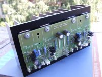
My P3A sounds very good indeed! I have three original ESP pcbs and this is the first that I assembled for initial testing. There was no matching of any transistors (not even LTP transistors) because I wanted to hear how the amp sounds in it's worst form. I used MrEvil's cap multiplier PSU and all interconnects and loudspeaker cables are worst there is: loudspeaker cables are 2x0,75mm2 lamp cable and interconnects are the crap cables that you get with mass produced gear. Preamp I used for initial testing was an old opamp based preamp without tone controls using NE5534. My P3A was biased at only 30mA per output pair. For tests I used Ron Carter's "Stardust" CD played on my Marantz CD57MK2.
Contrary to what some people think about this circuit (based only on looking at the schematics) this is exceptionally good sounding amp. I recently had a chance to hear NAIM NAIT XS and I must admit that I like P3A much more. I always liked the sound of quasi complementary output stages more than EF, but Sziklai is much better than both. There is no doubt that in the future I shall focus on Sziklai output stages.
What I like in this amp is:
1. Huge soundstage
2. No usual listening fatigue that is present with most voltage feedback topologies
3. The sound is detailed and fast
4. Very good dynamics
I have no doubt that in the voltage feedback power amp category using simple circuits this is
winning product. For the future P3A builds I shall try different semiconductor combinations (superior Sanyo VAS tranies and Sanken Base Island LAPT outputs 2SA2223A/2SC6145A).
A very enthusiastic rap, ivanlukic. I think it's great to lavish the best we can afford on designs or builds that most please us - it's a natural urge but may I add a word of caution:.... For the future P3A builds I shall try different semiconductor combinations (superior Sanyo VAS tranies and Sanken Base Island LAPT outputs 2SA2223A/2SC6145A).
Much of the good sound, soundstaging etc. we look for in the SQ of a lot of audiophile gear is actually determined by harmonic distortion - selectively chosen or "filtered" by choice of topology and parts. You may find that dropping in ultra high performance parts, like the LAPTs, counterproductive - maybe even de-stabilising, as I have found in some other old but good sounding designs. As you mention the Nait, the NAP 90 and Naits used craptanium TO220 silicon of pretty poor linearity (similar to later BD911) and whilst they sound passably Naim (firesuit on!), the standard NAP designs used something better with more capable drivers. These were an extreme example of a rationalised parts inventory, In my view.
Still, YMMV with the combination of devices in the output stage and the amount of compensation, so I hope you will still be pleased with the results. However, do use a scope to ensure you have no HF oscillation or brief bursts excited by the signal. Good luck
")
Last edited:
Nice to hear from you Ian!
Yes, I was too enthusiastic and very much pleased with the results obtained with the parts at hand. Thanks for the useful comments. I shall have to rethink my intention to use super parts for P3A. (I hate to desolder parts that are not working as they should.) I have some Sanyo 2SA1538 which I wanted to use at VAS position even for this first build. But now I am not sure that 400 MHz VAS transisitor is a good idea. The amp sounds so good with 2SB649A for VAS that I am unwilling to experiment in the wrong direction.
Yes, I was too enthusiastic and very much pleased with the results obtained with the parts at hand. Thanks for the useful comments. I shall have to rethink my intention to use super parts for P3A. (I hate to desolder parts that are not working as they should.) I have some Sanyo 2SA1538 which I wanted to use at VAS position even for this first build. But now I am not sure that 400 MHz VAS transisitor is a good idea. The amp sounds so good with 2SB649A for VAS that I am unwilling to experiment in the wrong direction.
I will partially agree with Ian here since it seems that Ian focus on detailed distortion as this rising with bias as said ( never confirmed by me though since i just got back from summer vocation meaning that there is 26 amplifiers behind me to be repaired ) will see that and get back ...
still here i d'like to add feed back from the repair industry ...we have costumers that prefer to loose a hand than loose a Quad 303 from their system If one looks at NVA today's ""product"" will find a TIP 142-147 based amplifier that has no Vbe multiplier so bias will vary depending on the use and output temperature and so is distortion and temperature ...still there is is people that think that NVA sound is unique ...Bull to my understanding
Since this is a thread about comparing it could be very nice to look at the same or other distortions of consumer or other designs .
I still believe that one way or another distortion or not there is something magic in the P3A and many listeners will agree with me ....
Kind regards
Sakis
Hi Sakis, 'hope you had a good vacation.
I know what you mean about the many awful old designs, based on Darlington industrial types. Whilst we can make any silicon produce audio, I have measured some designs, copied by kids from small websites and I found it crazy to see the very high 10kHz distortion. One design was above 1%. The kids who built it thought the amp. sounded great, when on the edge of spitting at HF and very unnatural imaging in the midrange. It was just a fun toy until they got bored with it, like a lot of DIY that is just too basic or badly designed, if at all.
I don't agree with heavy-handed approaches to enhancing the sound of amplifiers but there are enough big name brands that get big ticket prices when the effects desired are very subtle (below .05% THD) and trimmed "just so". Yes, tell me all about Goldmunds and distortion, for example.
Some music forms, such as dense orchestral, choral and "busy" popular music compositions sound woeful in the mud of a lot of competing distortion. It seems a waste of time to build amplifiers that only sound good with sparse Jazz solos, ambience music, or other simple forms, which many simple little class A amps seem to excel in. If you want to enjoy all types of music, that distortion has to be cut drastically, though not as low as 1ppm/20KHz distortion some guys seem compelled to aim for.
Any way you assess P3a, it's not a low THD design, at 0.04% 1kHz, it's hard to imagine harmonic distortion not having quite a bit to do with SQ but magic does? Ahem!..You already know the answer to this and you can see it on the analyser or soundcard, if you are set up for it. The problem, as I see it, is that people don't like to be told that it's the distortion they like - that dirty word. It's like telling someone that their new $10k HT system is crap or their kids are ugly. That's where words like 'magic' come in to politely conceal the facts. I can't say I blame audiophiles for inventing their own sound terminology, but the basis for it needs to be mentioned somewhere in the thread.
You know guys who would rather lose a hand than their Quad 303? I have an original condition (though recapped) 303 that is otherwise as new. It sounds good, but nothing like quality, modern designs. I don't think I'd lose a hand for its sound quality but it sure is 'handy' to have a neat, small footprint amp like this, that fits anywhere, is bulletproof and a statement in style.
Hmmm...wonder what happened to style with all these same-same rack cases?
Here might be an issue to add from the history aspect !
Found my self another commercial amp ( very commercial ) that is designed sziklai style with more than one pair in the output (2 pairs ) features VI limiting , ballast resistors for the emitters but also 0.1R ballast resistors for every npn or pnp sziklai pair/ set .
The marantz 2325 ! Its the family of 22xx looks integrated radio amp and 2325 should be the flagship of the line ...
Amplifier is under repair and i cannot comment about the sound will try to do that after the repair and intention will be to look at the main amp only and skip the preamp since the complexity of the front panel is way too messy .
So for some reason seems that the Japanese also walked that path once upon a time
Anybody willing to do some checking or some reading schematic is available and comments also very welcome
Kind regards
Sakis
OK, here you go - a clean but finely detailed schematic of the 2325 at AK forum. This is the Euro version but you can get a US version too.
It seems that the output transistors are mounted on flying leads - something we wouldn't do now, particularly with CFP stages. The arrangement of several resistors, 1 for each emitter to ensure current sharing and another in series with all is the same as a lot of old CFP designs, as I recall. Funny enough, if you look at Douglas Self's blameless CFP design, he dispensed with the current sharing resistors and used a single 0R1 emitter resistor for both transistors. It's been commercially available for many years now so it's obviously stable and reliable.
It seems that the output transistors are mounted on flying leads - something we wouldn't do now, particularly with CFP stages. The arrangement of several resistors, 1 for each emitter to ensure current sharing and another in series with all is the same as a lot of old CFP designs, as I recall. Funny enough, if you look at Douglas Self's blameless CFP design, he dispensed with the current sharing resistors and used a single 0R1 emitter resistor for both transistors. It's been commercially available for many years now so it's obviously stable and reliable.
Member
Joined 2009
Paid Member
With absolutely no matching of any of the transistors offset is 10mV for one channel and 25mV for the other and stable from first power up. I consider this very good results for amp with unmatched transistors. The sound is very clear even at high power. I am using professional studio monitor loudspeakers which can handle high spl without compression and distortion. Therefore, my conclusion is that, for 60W/8Ohm amp, loudspeakers will be the most limiting factor. In home environment loudspeakers will start to distort seriously much before P3A starts to clip. Most HiFi loudspeakers do not have voice coils of sufficient diameter and thermal rating and I am afraid that fact will influence subjective evaluation of this excellent simple design. For proper evaluation of this design one should try high quality/high power/high efficiency loudspeakers. Something like high quality PA loudspeakers or HiFi speakers with enormous power capacity - speakers with big voice coils like used in ScanSpeak or Dynaudio drivers.
- Home
- Amplifiers
- Solid State
- P3A Comparison table ( long .... )