hello Dear Friends,
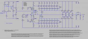
this is the Tina 7 T.I. simulation of the Kuroda TL071 60W FET Amp published in September 1982.
More info here : poweramp
The attached .zip contains the schematic ready for simulation.
Cheers,
Steph
this is the Tina 7 T.I. simulation of the Kuroda TL071 60W FET Amp published in September 1982.
More info here : poweramp
The attached .zip contains the schematic ready for simulation.
Cheers,
Steph
Attachments
-
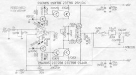 KURODA TL071 60W FET AMP (1982) - original drawing.JPG36.5 KB · Views: 3,277
 -
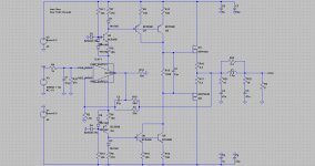
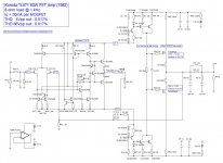 KURODA TL071 60W FET AMP (1982) V1.00 - schematic.JPG191.5 KB · Views: 2,412
 -
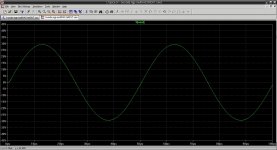
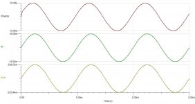 KURODA TL071 60W FET AMP (1982) V1.00 - system waveforms sinus 15mV in.JPG92.9 KB · Views: 2,007
 -
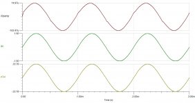 KURODA TL071 60W FET AMP (1982) V1.00 - system waveforms sinus 1500mV in.JPG91.8 KB · Views: 1,662
 -
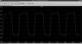
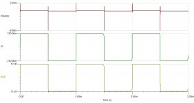 KURODA TL071 60W FET AMP (1982) V1.00 - system waveforms square wave 750mV in.JPG64 KB · Views: 1,556
 -
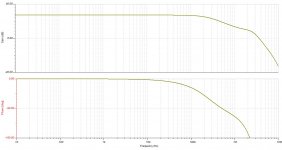 KURODA TL071 60W FET AMP (1982) V1.00 - gain & phase.JPG145.8 KB · Views: 734
 -
Kuroda TL071 60W FET Amp (1982).zip402.3 KB · Views: 560
hello Dear Friends,
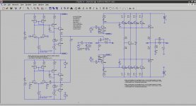
this is the LTspiceIV simulation of the Kuroda TL071 60W FET Amp published in September 1982.
More info here : poweramp
The attached .zip contains the schematic ready for simulation.
Cheers,
Steph
this is the LTspiceIV simulation of the Kuroda TL071 60W FET Amp published in September 1982.
More info here : poweramp
The attached .zip contains the schematic ready for simulation.
Cheers,
Steph
Attachments

hi,
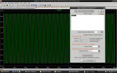
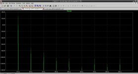
helmutsennwald and analogspiceman helped me for improving the .TRAN directives, in order to get a high-resolution FFT plot under LTspiceIV Waveform Viewer, with a noise floor of -180dB, quite a spectacular performance.
I wanted a FFT look and feel equal or better than what we get using spectrum analyzers like B&K and AudioPrecision. In order to get sharp spectrum lines, a frequency resolution of 10Hz got chosen, translating into a 100ms analysis window.
1 - In order to decrease the physical noise floor, one must allow the circuit to settle, and this is of big importance if spice had trouble (which is nearly always the case) finding the DC operating point. Failure to do this generates a physical -120dB noise floor. The .TRAN directive must thus become something like .TRAN 0 101ms 1ms for allowing spice to gently deal with the circuit during 1ms, before storing the next points that will be used for a 100ms FFT.
2 - One must force spice to generate all the points that the FFT will need, without interpolating some portions of the signal. This is done by adding a 4th parameter to the .TRAN job : the max step, which is chosen equal to 1 microsecond. Is this 4th parameter equal to a separate option "maxstep = 1u" ?
3 - One must force spice to refine each point, considering that a point gets properly done with a tolerance of only 1e-6 during the iterative matrix solving process. This is done with the option "reltol=1e-6".
4 - One must de-activate the waveform compression spice is using by default after completing the .TRAN job. The de-activation of the waveform compression is done by the option "plotwinsize = 0"
5 - One must ask spice to use double-precision arithmetics. This is done by the option "numdgt = 15". Actually, the LTspiceIV UserManual manual says that any parameter greater than 6 activates double precision arithmetics.
6 - The FFT processor must be configured for high resolution. This is done by asking a 4Meg points FFT, without windowing.
see http://tech.groups.yahoo.com/group/LTspice/messages
and enter "FFT after .TRAN" in the search box
The results are self explaining (see the pictures).
Use the .zip if you want to run the FFT plot.
Quite worrying is that the "old fasion" .FOUR says now that the distorsion is very low. I let you discover the spice log :
****
Circuit: * C:\LTspice Simulations\Kuroda TL071 60W FET Amp (1982)\Kuroda TL071 60W FET amp (1982) - with improved .TRAN directives.asc
Early termination of direct N-R iteration.
Direct Newton iteration failed to find .op point. (Use ".option noopiter" to skip.)
Starting Gmin stepping
Gmin = 10
Gmin = 1.07374
Gmin = 0.115292
Gmin = 0.0123794
Gmin = 0.00132923
Gmin = 0.000142725
Gmin = 1.5325e-005
vernier = 0.5
vernier = 0.25
vernier = 0.125
Gmin = 5.90244e-006
vernier = 0.0625
vernier = 0.03125
vernier = 0.015625
vernier = 0.0078125
Gmin = 5.93519e-006
vernier = 0.00390625
vernier = 0.00195313
vernier = 0.000976563
vernier = 0.000488281
Gmin = 5.9417e-006
Gmin = 0
Gmin stepping failed
Starting source stepping with srcstepmethod=0
Source Step = 3.0303%
Source Step = 25.7576%
Starting source stepping with srcstepmethod=1
Source Step = 3.0303%
Source Step = 25.7576%
Source Step = 26.1245%
Source stepping failed
Trouble finding operating point....skipping operating point for Transient analysis.
Heightened Def Con from 1e-011 to 3.701e-008
Fourier components of V(vout)
DC component:-0.000817022
Harmonic Frequency Fourier Normalized Phase Normalized
Number [Hz] Component Component [degree] Phase [deg]
1 1.000e+03 2.252e+01 1.000e+00 -0.27° 0.00°
2 2.000e+03 6.171e-05 2.741e-06 6.73° 7.00°
3 3.000e+03 3.344e-05 1.485e-06 83.83° 84.10°
4 4.000e+03 5.249e-06 2.331e-07 -141.12° -140.85°
5 5.000e+03 5.222e-06 2.319e-07 -24.32° -24.05°
6 6.000e+03 3.983e-06 1.769e-07 -120.34° -120.07°
7 7.000e+03 5.265e-06 2.338e-07 -8.37° -8.10°
8 8.000e+03 5.038e-06 2.237e-07 -131.99° -131.72°
9 9.000e+03 5.909e-06 2.624e-07 -9.36° -9.09°
Total Harmonic Distortion: 0.000317%
Date: Tue Apr 06 02:26:47 2010
Total elapsed time: 34.250 seconds.
tnom = 27
temp = 27
method = modified trap
totiter = 456927
traniter = 450738
tranpoints = 130564
accept = 124155
rejected = 6410
matrix size = 132
fillins = 302
solver = Normal
Thread vector: 38.5/26.4[2] 16.6/11.7[2] 6.0/5.2[2] 5.5/4.5[2] 2592/500
Matrix Compiler1: 30,4 Ko object code size 17.6/12.9/[7.4]
Matrix Compiler2: 17,2 Ko object code size 8.4/9.6/[4.7]
****
This means that all my former considerations about distorsion may need to be reassessed. However, I doubt that a TL071-based amp, can have a distorsion as low as 0.000317%. Formerly, not using hig-res .TRAN directives, the displayed distorsion by the non hi-res .TRAN directives was 0.017%. And I found this to be a realistic and reliable figure.
So, where is the truth ?
Hi-res .TRAN or no hi-res .TRAN ?
Cheers,
Steph
Attachments
-
 KURODA TL071 60W FET AMP (1982) - with improved .TRAN directives.jpg253.7 KB · Views: 977
 -
 KURODA TL071 60W FET AMP (1982) - FFT settings.jpg439.1 KB · Views: 651
 -
 KURODA TL071 60W FET AMP (1982) - FFT sinus 1K plot.jpg79.8 KB · Views: 432
 -
Kuroda TL071 60W FET Amp (1982) - with improved .TRAN directives.zip405.7 KB · Views: 376
Unfortunately, I don't have the original article on hand (I can check it when I go back to Japan next time, though), but 0.017% sounds more reasonable for this topology.
By the way, as I understand the reason you are studying this topology is to avoid either obtaining dual JFETs or matching singles. JFET like 2SK30A (GR) is cheap enough to pile up (way cheaper than output devices) and the result would be satisfying after matching them with small effort and time. I believe it's worth a consideration.
Best regards,
Satoru
My simulator says that this circuit doesn t work...
Output DC operating point is at +36V with the
components values displayed in this schematic.
Did i miss something ?...
Output DC operating point is at +36V with the
components values displayed in this schematic.
Did i miss something ?...
What simulator ? What schematic ? What TL071 implementation ? Pls attach your spice log, and I'll see what I can do for you.My simulator says that this circuit doesn t work...
Output DC operating point is at +36V with the components values displayed in this schematic. Did i miss something ?...
Hi Satoru, yes indeed at the beginning of the process, I was in search of an expedite way for replacing the hard-to-find matched JFETs, by an audio opamp as front-end. Then came the issue of the TL071 official Texas Instruments subcircuit mis-simulating the power supply pins, as explained into the "tl071-hand-made-simulation-using-discretes" thread. Over there you made a crucial contribution in bringing the genuine Toru Kuroda schematic we are dealing with - and I am taking the opportunity here to thank you for this. I then realized that this Kuroda schematic was a piece of electronic art, simple, efficient. At the moment, my opinion is that this Kuroda schematic is the most practical, elegant way to achieve a substantial dynamic range extension at the driver level, the driver however not being Class A anymore when fully driven. This topology has functional similarities with "current feedback" opamps, as the whole Kuroda amp may be perceived as a "current feedback" opamp. One day janneman should agree on that. It also reminds me the preoccupation of Giovanni Stochino, with his "non slewing" power amps described in Wireless World, much later. And, regarding Kuroda schematic, we have not spoken yet about the local feedback resistor, the 390 ohm resistor injecting the output of the power amp into the output of the opamp, with the 150 ohm as voltage divider. One way to look at this, is to realize that this arrangement forces the opamp to work with a voltage swing at the output, that's a lot more than if the 390 ohm resistor was not there. One may thus say that this arrangement helps the opamp regaining a nominal working range, with a substantial voltage swing at the output, hence a decent voltage gain (about 4x), and this is a proper way for getting his internal VAS (and 18pF compensation capacitor) working as usual. This may help stability, and this may help tonal signature consistency.I understand the reason you are studying this topology is to avoid either obtaining dual JFETs or matching singles. JFET like 2SK30A (GR) is cheap enough to pile up (way cheaper than output devices) and the result would be satisfying after matching them with small effort and time. I believe it's worth a consideration. Best regards, Satoru
So now, I am concentrating on this particular topology, willing to understand it in detail, willing to see what are the followups.
There is one notorious followup, described in the application information of the Analog Device SSM-2131 opamp (previously made by PMI). The followup can be found as Figure 6 on page 7-86 of the AD/PMI Analog Integrated Circuits Data Book Vol #10 Copyright 1990.
If somebody could provide a .pdf of this, that would be very helpful.
COLBY got inspired by the AD/PMI SSM-2131 arrangement. He designed a power amp.
It is here : members.aon.at/viellieb/amps/pics/amps/cfbamp.pdf
See attached.pdf.
I think there is a clear future for power amps using audio opamps as front-ends, especially if it can be proven that the opamp is working within his nominal enveloppe (gain, load, frequency range), bringing thus his tonal signature in a smooth way. Kind of design philosophy for the future. Use the audio opamp of your choice in your power amp.
With the advent of Class-D amps, it is needed to find new arguments in favour of Class AB amps. It is thus needed to get the Class AB amps incorporating the latest silicon advances like ultra low noise, ultra low offset, laser-trimmed font-ends. You will only get this if you are relying on an opamp as front-end.
My understanding is that the Kuroda is a solid, simple, efficient building block, that may be used "as is", or in more complicated arrangements like :
- The "Quad 405 Bridge" in pure Class B like the original, but also in Class AB
- Technics "Class AA bridge" in full Class A like the original, but also in a Class A voltage amp + Class AB current amp
- The "Soft Non-Switching Class AB", a new Class AB sub-class, now working on simulation
The use of SMDs may allow PCBs as compact as the ones used with TDA7293 or LM3886. The advent of lateral NMOS + PMOS in a single TO-247-5L package (Magnatec Alfet) will provide a nice simplification. Now that Magnatec is busy with a 5-terminal TO-247, why not a 7-terminal TO-247 in the future, with 2 pins for thermal management ?
I'ts going to be fun again ! Soon, we'll be again in the the golden age of analog amplification ! Time to reopen our files ...
It is amazing to see LTspiceIV being able to test and solve things today, that remained untested and unsolved 30 years ago.
All we need now, and very urgently, is a "blameless" digital crossover, "blameless" audio DAC and "blameless" volume control, for feeding those next-gen (or next-gem ?) analog amplifiers.
Otherwise analog amplification will be defeated by Class-D amps, bitstream-fed ! For sure. And sooner than we may think.
Cheers,
Steph
Attachments
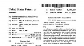
This followup is the famous "Alexander Current-Feedback Audio Power Amplifier"There is one notorious followup, described in the application information of the Analog Device SSM-2131 opamp (previously made by PMI). The followup can be found as Figure 6 on page 7-86 of the AD/PMI Analog Integrated Circuits Data Book Vol #10 Copyright 1990.
If somebody could provide a .pdf of this, that would be very helpful.
a) presented in the 88th AES convention March 1990,
b) explained in the SSM-2131 data sheet,
c) re-explained in the AN-211 Analog Device Application Note,
d) patented in the US patent #5,097,223 filed May 22nd 1990 and granted Mar 17th 1992.
See attached .zip file.
Due to file size restrictions, I was unable to attach the AN-211 Analog Device Application Note, but you may find it here :
http://www.analog.com/static/import...tes/58052492001115525484056221917334AN211.pdf
What is the Japan patent #37717 dated 4/81 cited on the Alexander patent cover page ? The Kuroda 1982 implementation maybe ?
The 88th AES Convention paper may be downloaded here :
AES E-Library: A Current-Feedback Audio Power Amplifier
Cheers,
Steph
Attachments
-
 The Alexander Current-Feedback Power Amplifier 1990 - Analog Devices AN-211.jpg120.9 KB · Views: 1,087
 -
The Alexander Current-Feedback Power Amplifier 1990.zip886.8 KB · Views: 395
-
 The Alexander Current-Feedback Power Amplifier 1990 - U.S. Patent front page.jpg188.8 KB · Views: 898
 -
 The Alexander Current-Feedback Power Amplifier 1990 - AES 88th Convention 1990.jpg86.2 KB · Views: 563
Last edited:


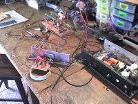
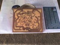
hello Ismar, have you considered re-issuing it using a tiny PCB with surface mounted components and the two MOSFETs screwed on a L-shaped metal bar ? It would be a nice alternative to chipamps. No capacitor in the feedback network is feasible if using a less than 1mV offset FET-input opamp.
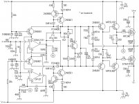
hello Ismar, a few questions about your Kuroda implementation.
The 68pF as Miller capacitors (C12 C13) seem oversized. You really needed them so big for getting a stable amp ?
There is no 33nF capacitor in parallel with Q7 on the bias voltage. Have you tried with and without, or playing with the value ?
The VAS loop gain is four times higher than the original Kuroda. Q4 and Q2 have a 22 ohm emitter resistor (instead of 50 ohm), and the base voltage they receive come from 390 ohm (instead of 270 ohm). You needed such gain boost for achieving a decent 1kHz distorsion figure ?
The TL071 supply current is not externally limited. In your implementation it only gets limited by the internal TL071 output stage current protection (15 mA or so near ground) but such value may be too high and cause unstability or damage when the amp enters slew-rate limitation. In the Kuroda implementation it gets limited to approx 6.5 mA (one diode voltage drop on 100 ohm).
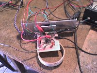
Hi steph
The idea of assembling SMD is legal and
this was the best way to stabilize the circuit.
The tests were done with electrostatic speakers.
I used the input signal, 100Hz, 440Hz, and 1Kz 10Kz, square wave, with 100mVpp.
C12, C13 and C16, C17 were necessary experimentally, to remove parasitics oscillations.
The harmonic distortion is approximately 0,015 to 1 kHz using HP 3580A (Spectrum Analyzer).
The amplifier work well!!!
The circuit needs rather more time for development.
I will test the changes you are indicating.
thanks

Warning ! BJT output schema in unstable when applying a square wave at the input.
MOS output schema is perfectly stable when applying a square wave at the input.
MOS output schema is perfectly stable when applying a square wave at the input.
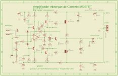
kuroda
ngp = no ground pollution (the 2nd OPAMP acts as virtual ground)
multiVAS = parallelized transistors in the VAS
fetOUT = lateral FET output devices
looks promising on simulation
are there better LTspiceIV models for lateral MOSFETs ?
ngp = no ground pollution (the 2nd OPAMP acts as virtual ground)
multiVAS = parallelized transistors in the VAS
fetOUT = lateral FET output devices
looks promising on simulation
are there better LTspiceIV models for lateral MOSFETs ?
Attachments
-
kuroda ngp multiVAS fetOUT.asc.txt17.4 KB · Views: 226
-
 kuroda ngp multiVAS fetOUT.jpg187.3 KB · Views: 712
 -
 kuroda ngp multiVAS fetOUT - distorsion.jpg177.6 KB · Views: 658
 -
 kuroda ngp multiVAS fetOUT - square wave.jpg204 KB · Views: 563
 -
 kuroda ngp multiVAS fetOUT - sinus 20 kHz.jpg256 KB · Views: 217
Hello Steph,
Great Kuroda Amp!!!!!
Thanks for any information and simulations on LtSpyce.
Really,
When I use BJT becomes more unstable the output with square-wave.
I use LTSpyce for some simulations, but prefer to mount the breadboard and make measurements using a model 475 Tektronix oscilloscope (BW 300Mhz).
I am doing some modifications in my circuit.
Big hug, and sorry for the delay in responding ...
***
Hi Steph,
When mounting the amplifier for use in Eletrostatic Speaker, parasitic oscillation appeared.
So tentatively, I was adding feedback capacitor, but not enough.
Another capacitor integrator Muller, was necessary.
Could not understand the reason, but eliminated the oscillations.
How no longer have the eletrostatic speakers, I'll do more experiments!!!..
Thanks for the help!!
Hugs!!
- Status
- Not open for further replies.
- Home
- Amplifiers
- Solid State
- Kuroda TL071 60W FET Amp (1982)