Today I get an integrated amplifier for repair. It is a NAD 310. The reason was quickly find: burned PCB and broken solder points arround the zener's for the baxandall equalizer stage.
But curious and new for me is the output power buffer topology:
1) one N-Channel MOSFET in the positive half (Philips/NXP BUK-555, TO-220)
2) one PNP BjT in the negative half (Sanyo 2SB817, TOP-3)
What kind of push pull output buffer is this (so called ?????) ? Who knows more about this, e. g. AES papers and other amplifier models, where such power buffers are in use?
Schematic for NAD-310 you will find here:
https://www.google.de/url?sa=t&rct=...Manual-2.pdf&usg=AOvVaw0XIKknNVKvf3Uy-CKv0T3i
NAD 310 - need some info
Last edited:
Capacitor coupled to the speaker (UCK!), single supply amplifier.
Definitely better than serial relais contact against dc protect, even by use of cheap caps.
in my previous post the schematic URL was wrong:
Nad Download Page - nad-310-integrated-amplifier-schematic.pdf || ABELtronics
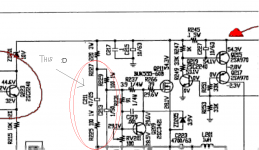
And exactly what is C225 (33p) and R255 (100K) doing for us?? Why is some of the (high frequency??) left channel, via these two parts, fed back into the right channel input(Q203 emitter)?? Why the cross channel feedback??
Didn't get me wrong, if you are happy with the sound, keep using it. It's just that I suspect there are "better" amplifier out there, IMHO. I listened to a Heathkit AA-15 that had a 'lytic for DC blocking in series with the speaker and was a single supply amp for years. I was happy with it. The NAD circuitry is just not really revolutionary.
Didn't get me wrong, if you are happy with the sound, keep using it. It's just that I suspect there are "better" amplifier out there, IMHO. I listened to a Heathkit AA-15 that had a 'lytic for DC blocking in series with the speaker and was a single supply amp for years. I was happy with it. The NAD circuitry is just not really revolutionary.
Tief,
This topology measures badly (high even order), but sounds very good.
A quasi version of this approach is also extant from the same era. N type mosfet at pos rail, pnp driver and npn output at neg rail. This sounds very good, too.
Give it a good listen once you fix it. You will be very surprised.
Hugh
Like Hugh (Mr.AKSA) said, this is a very musical sounding topology - I use it for my guitar amps, except that I use NPN bjt and IRFP9140. Not too bad for music listening, but fabulous for electric guitar or vocal usage !
And the output capacitor helps prevent blown speakers when playing "live" ...
And the output capacitor helps prevent blown speakers when playing "live" ...
Most positive feedback amplifier has its disadvantage at high frequency, but this is might different because of the buffer has faster and separately follow the stage before. Lower side BJT gaining the current source, and upper mosfet gaining that hot resistor.
It was good in past, but it is not interested any longer because of high THD and hot VA stage.
It was good in past, but it is not interested any longer because of high THD and hot VA stage.
Tief,
This topology measures badly (high even order), but sounds very good.
Hugh
Yes, in case of low idle current between 30mA and 100mA (badly measuring results still present, independend of the topology).
If I choice an idle current of 1,3A, this topology measures very good (see attachement - please ignore the device numbers from my schematic because it's not the same than by orig NAD schematic).
onto aban: Where you have discover the PFB (positive feedback) ? I find only a NFB network (negative feedback - consists of 820R/10R/1MF for AC and 3K3 for DC).
stoc005: integrated RIAA head amp by an integrated amp is a very bad solution for various reasons. The royal way is still an external RIAA device like this:
NAD Electronics :: PP-2 Phono Preamplifier
Cheap and high quality at the same time.
Attachments
Last edited:
yes, but on the other hand you cannot expect low IM/THD miracles, independend, which circuit topology is present. Here high order distortion above H4 are arround 30db enhanced (see attachement). This fact is to observe basicly by all me known analoge power amp topologies with only low idle currents trough the output stage.hi thief, you have improved its simulation result, but 1.3A is about to think another way, it is too hot for cheap amps.
I also don't understand the aim of R225 in series to C211 in your marked aera from the PNG file in your last post
Who was the developer from this circuit topology? Maybe Bjørn Erik Edvardsen?
http://en.wikipedia.org/wiki/NAD_Electronics
Attachments
Last edited:
Tief,
What conclusion do you draw from this? That higher bias reduces the higher order artefacts, or that the topology is flawed?
Have you listened to it yet? I'm interested in your assessment......
Cognitive dissonance, anyone?
Hugh
higher bias in direction to classA reduces always the higher order artefacts independend of the topology.
The NAD310 power amp stage sounds great by the use of external universal power supply, but in original condition the sound is worse cause the too small internal transformer and caps.
At this comparable test I choise in both cases an idle current arround 30-40mA through the output.
For aprox. 10 seconds I was able to check the sound by 500mA idle current through the output (only with external power supply). This means ClassA up to a certainly output level.
This feeling sound enhancement here is also large, but mainly in the upper range (moore smooth and musical sound). And in completely other kind than the difference between internal and external power supply.
Such observations I have make by a lot of such amplifier tests by a wide range of PP models/topologies.
My conclusion is clearly, that all sound differences from circuit topologies itself clearly very low (maybe even completely negligible), comparable to that one from different power supplies, different GND wiring management and that one between ClassA and ClassB. Sometimes more than one voltage gain stage in the negative feedback loop can produce negative audible effects, especially in case of classB.
Until this day I haven't discover a power amp driver stage (voltage gain front end), that deliver nearly the same acoustical result both at Class-B (30-40mA) and pure ClassA.
From this arises the question for me what is the justification for often very complex power amp topologies there.
Please note, I am not an english man and therefore I cannot make a comparable test describtion so exact than the authors from the "Absolute Sound" - sorry.
Last edited:
Sounds pretty good to me. I agree with you, and feel your observations are keen and credible.
I'm not quite sure that topologies all sound the same, and that differences are ascribed to bias levels however, but that's just my opinion and could well be wrong.
OTOH, I'm not convinced that symmetrical, complementary designs always sound best either. There is something else at play which I might describe as 'psychoacoustics', the way in which music is perceived by the human mammal.
The machine part is straightforward. We can now achieve 0.001% distortion without too much difficulty using modern semis. But the man part of the interface is much more tricky.....
Hugh
The machine part is straightforward. We can now achieve 0.001% distortion without too much difficulty using modern semis. But the man part of the interface is much more tricky.....
Hugh
If you achieve 0.001% distortion also at frequencies arround 100KHz you can assume, that such amplifier sounds still good. Unfortunately in most cases the choised frequencies for THD measuring are only 1 KHz or max 10 KHz. In this aera most bad sounded amps delivers still satisfy THD results.
read in this case my posts about
http://www.diyaudio.com/forums/solid-state/150024-class-inherent-disadvantages.html
so as post #142 about
http://www.diyaudio.com/forums/solid-state/114865-densen-amp-15.html
and have a look to
http://www.diyaudio.com/forums/pass...m-results-pass-x-series-us-pat-5376899-a.html
Most of the members don't share my views on how you can read from the replies, but I'm sure I'm right.
I also don't understand the aim of R225 in series to C211 in your marked aera from the PNG file in your last post
That aim just series of positive feedback network.
Positive FB applied to many old solid state amplifiers. It has significant effect on loudspeaker movement. But later, when more power rating created to drive multiple loudspeakers, the sound wave of loudspeaker stack are difficult to be maintained, and the sound just troublesome. Now this type of feedback just history, but old amps only.
I am still want to know, who was the developer.yes, but on the other hand you cannot expect low IM/THD miracles, independend, which circuit topology is present. Here high order distortion above H4 are arround 30db enhanced (see attachement). This fact is to observe basicly by all me known analoge power amp topologies with only low idle currents trough the output stage.
I also don't understand the aim of R225 in series to C211 in your marked aera from the PNG file in your last post
Who was the developer from this circuit topology? Maybe Bjørn Erik Edvardsen?
NAD Electronics - Wikipedia, the free encyclopedia
Member
Joined 2009
Paid Member
Stone soup - Wikipedia, the free encyclopediawhat is the justification for often very complex power amp topologies
Stereo Widening Circuit Nad 3010 Removal
These parts are indeed a stereo widening circuit., `
I did experiment lifting the legs of the capacitors to disconnect the circuit.
On some music, with the widening circuit connected it sounded fantastic and I was thinking oh wow this is a great circuit., On other tracks the widening circuit made the sound thin and scattered and destroyed the sound stage vocals and beauty in a song.
Ultimately I have left the widening circuit disconnected. Overall it is better without it. But I understand NAD's decision to include the circuit. It would make the amp stand out in the show room compared to other similar amps on certain tracks and lead to more sales for certain.
A switch to turn the widening on and off is a good idea. Might as well take advantage of it when it works. But the trouble is It can work well on one track of an album but not the next track.
The best upgrade I have made to this amp is replacing the 1000uf feedback capacitors with Elna Silmics C207,208. Everything top to bottom became clearer and cleaner. Upgrading the output capacitors to Nichicons improved the high frequency responce which I think was a little dull.
This is a great amp. It was my first hifi amp. Bought new in 95. I've blown the FET output transistor 3 times. I have had other amps come and go but this 310 has always stayed as a reference.
I have heard warmer amps, more clinical, better detailed and less detailed. This is kind of mr average right in the middle. It is well balanced and if not perfect, it is always pleasurable to listen to music through this amp so it has always stayed.
Also in responce to the can the pre amp be separated from the power amp. I have tried this, but not been able to get it to work well. I suspect it is a problem with impedance matching. I can get sound out of the pre and into the amp but it is not right. Too harsh and bright sounding.
And exactly what is C225 (33p) and R255 (100K) doing for us?? Why is some of the (high frequency??) left channel, via these two parts, fed back into the right channel input(Q203 emitter)?? Why the cross channel feedback??
These parts are indeed a stereo widening circuit., `
I did experiment lifting the legs of the capacitors to disconnect the circuit.
On some music, with the widening circuit connected it sounded fantastic and I was thinking oh wow this is a great circuit., On other tracks the widening circuit made the sound thin and scattered and destroyed the sound stage vocals and beauty in a song.
Ultimately I have left the widening circuit disconnected. Overall it is better without it. But I understand NAD's decision to include the circuit. It would make the amp stand out in the show room compared to other similar amps on certain tracks and lead to more sales for certain.
A switch to turn the widening on and off is a good idea. Might as well take advantage of it when it works. But the trouble is It can work well on one track of an album but not the next track.
The best upgrade I have made to this amp is replacing the 1000uf feedback capacitors with Elna Silmics C207,208. Everything top to bottom became clearer and cleaner. Upgrading the output capacitors to Nichicons improved the high frequency responce which I think was a little dull.
This is a great amp. It was my first hifi amp. Bought new in 95. I've blown the FET output transistor 3 times. I have had other amps come and go but this 310 has always stayed as a reference.
I have heard warmer amps, more clinical, better detailed and less detailed. This is kind of mr average right in the middle. It is well balanced and if not perfect, it is always pleasurable to listen to music through this amp so it has always stayed.
Also in responce to the can the pre amp be separated from the power amp. I have tried this, but not been able to get it to work well. I suspect it is a problem with impedance matching. I can get sound out of the pre and into the amp but it is not right. Too harsh and bright sounding.
- Status
- This old topic is closed. If you want to reopen this topic, contact a moderator using the "Report Post" button.
- Home
- Amplifiers
- Solid State
- New Push Pull Buffer Approach for special Kind of THD - MOSFET & BjT - New for me