Yes LED as clip, but in series with NSL32 integrated LED if you want to have clip/limit LED.
apex,
in post #349 you said 4k7 + led
should be top side of led or bottom,as per post 936?
adding more output
but i see pcb is getting longer using original lay out
is there anybody can help designing pcb ,not making it longer upon adding more trannies,making long pcb make it hard to find long heatsink,
something like this,
or separate driver and output board better
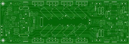
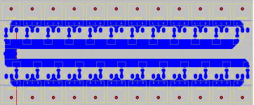
adding more output for stability and reliability,OK guys here is the top layer showing the 2 additional needed jumpers everything else same with the earlier b500 top layer except 2 more pairs and the four 0.33E resistor ........ plz some body print the pcb on a paper and tell me the length............
regards
sekhar
but i see pcb is getting longer using original lay out
is there anybody can help designing pcb ,not making it longer upon adding more trannies,making long pcb make it hard to find long heatsink,
something like this,
or separate driver and output board better
Attachments
look nice.have schematic and component layout?this b500?adding more output for stability and reliability,
but i see pcb is getting longer using original lay out
is there anybody can help designing pcb ,not making it longer upon adding more trannies,making long pcb make it hard to find long heatsink,
something like this,
or separate driver and output board better
apex,
in post #349 you said 4k7 + led
should be top side of led or bottom,as per post 936?
You can use NSL32 and add clip/limit LED, or not to use NSL32 and use clip LED instead led integrited in NSL32, 47k resistor instead integrited LDR.
look nice.have schematic and component layout?this b500?
This is H900.
h900 hard to me to find 2 differ voltage input.apex i want to winding toroid transformer. standart toroid using single wire or double for main output?i want produce 60 volt ac.if using double wire i know to get high current but need more wire and space.what u think mr apex>This is H900.
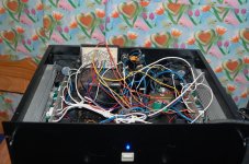
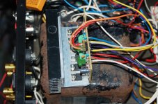
step drive TL072 connected on B500
Mile I've done connecting the Step drive to my B500 single channel and i felt/hear the difference so very load even i only use +/-75 +/-42 load 4 ohms 500 watts speaker..
and i just want to know how to determine if tl072 is really working ,i dont have scope i just have multi meter.
Mile I've done connecting the Step drive to my B500 single channel and i felt/hear the difference so very load even i only use +/-75 +/-42 load 4 ohms 500 watts speaker..
and i just want to know how to determine if tl072 is really working ,i dont have scope i just have multi meter.
Attachments
B500 WITH 12 O/P PAIR (X1500)
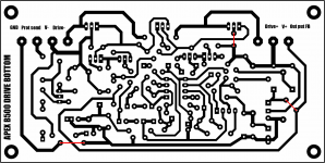
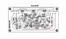
My earlier submission of b500 was nt liked much due to length pcb . So here is the solution in progress . B500 with 12 o/p pairs + driver board . I dont know wether it should be called b500 any more , with due permission from Miles we can call it
" X1500 " or some thing . The PCB length will not more than 295mm X 70mm.
here is the work on progress any suggestion will be welcome . I will include the vbe multiplier transistor on the main o/p board.
I need suggestions , advise etc etc ........
regards
sekhar
Attachments
Hi, Sekran.
Can you post PCB dimensions? Will it work in 2ohm with 6 pair of transistors?
Regards
i myself dont know the pcb dimention because i just edited the b500 pcb as a picture file so asked some one to print it and post the size . neways with 6 o/p pairs u feel safer with 4E load not 2E. Miles will educate us on this topic more as he much more experienced ...... and mihailo my name is " SEKHAR" not sekran
 :
:regards
sekhar
Mile I've done connecting the Step drive to my B500 single channel and i felt/hear the difference so very load even i only use +/-75 +/-42 load 4 ohms 500 watts speaker..
and i just want to know how to determine if tl072 is really working ,i dont have scope i just have multi meter.
Multi meter can read only DC or 50Hz RMS AC voltage. If you use LED instead NSL32, and run amp with 0,+/-42v,+/-75v rail voltage, LED will light on if you have 60v peak voltage on amp out with high level audio input. With low rail voltage of +/-42v, amp will clip at about 38v output voltage, and LED can't light on if step driver not work and not increase rail to +/-75v at peaks.
ok i will try again with clip led ..is it normal step drive circuit not heating up even on full volume?Multi meter can read only DC or 50Hz RMS AC voltage. If you use LED instead NSL32, and run amp with 0,+/-42v,+/-75v rail voltage, LED will light on if you have 60v peak voltage on amp out with high level audio input. With low rail voltage of +/-42v, amp will clip at about 38v output voltage, and LED can't light on if step driver not work and not increase rail to +/-75v at peaks.
Hi,hello everyone pls help me for XLR input with stereo bridge switch
if you have a balanced source fed in through an XLR plugged cable then you don't need a bridged switch. Each half of the amplifier will be driven by the hot or cold input pins.
Read Rane, Jensen, D.Self, ESP.
- Home
- Amplifiers
- Solid State
- 500W PA amplifier with Limiter