Hi everybody...
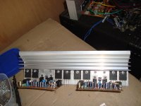
I'm just finished 1 pair
Hope everything gonna be okay
a few modification has been made
Nice and clean work
before power it up pls check ic it seems to be at wrong position pin4-vcc pin8 +vcc
http://www.ti.com/lit/ds/symlink/ne5532.pdf
Sorry my bad i see it on mirror
Last edited:
Nice and clean work
before power it up pls check ic it seems to be at wrong position pin4-vcc pin8 +vcc
http://www.ti.com/lit/ds/symlink/ne5532.pdf
Sorry my bad i see it on mirror
Thank you irvynejay...
& yes, I will check everything first before powering up
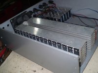
btw now I want to prepare the heat sink
just thinking how to make it good looking
any suggestion?
Hi! I'm new at this site, I want to build this circuit for my 400W/8r speaker. Can I get 300W with this circuit(with 4 pairs of transistors) on +-90V? And I also wanted to ask, what is that PRO output on the scematic? I guess it's some kind of protection, but I don't understand how it works.
Thank you for your help!
Thank you for your help!
For 300W into 8r0, use the standard Power Formula.
P = Vpk^2 / Rload / 2
Rearrange to get Vpk on the left.
Vpk = sqrt(P * Rload *2) = sqrt(300 * 8 * 2) = 69.3Vpk.
Supply rails @ +-90Vdc seem far too high for your target maximum power.
Vpeak of 69.3V and 8r0 loading implies ~8.7Apk when driving an 8r0 resistor load.
Design for three times this for a speaker demand, i.e. 25Apk
Each of the 4pairs will have to handle ~6.5Apk and when driving a severe reactance load @ ~60degree phase angle expect upto one supply rail voltage for Vce while passing that peak current. Look up the SOA and de-rate for temperature to see if your output device can pass 6.5Apk @ 69Vce when de-rated for Tc~50degC, for a short term pulse of 100ms and for 10ms and for 1ms and for 100us.
Now estimate what the devices can do with music.
Pass test but...
Hi everyone,
Hi jacobsetti, have you built it one?
Mr Mile will be answer you if you built one of this good amp")
Maybe 60 - 0 - 60 volt DC will give you 300w to 4R
see this one http://www.diyaudio.com/forums/solid-state/164093-100w-ultimate-fidelity-amplifier-92.html AX20
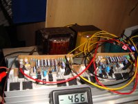
I made it, my B500
already on the heatsink & hope not too small
But:
1. Why offset just to high
as recommended 20mV or less, my B500 is
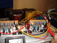
-466mV & -123mV
& the voltage
on 100ohm resistor is little below 0,5V
on base emitter KSE340(bias) is little below 2V
2. use 2 x transformer 50Vac but
DC after rectifier is 61VDC, should be 65-66VDC
(Vac is drop to 46Vac because test is at night)
Maybe bad caps or something?
Anyone please help, where do I start to check it out?
Regards
Hi everyone,
Hi jacobsetti, have you built it one?
Mr Mile will be answer you if you built one of this good amp
Maybe 60 - 0 - 60 volt DC will give you 300w to 4R
see this one http://www.diyaudio.com/forums/solid-state/164093-100w-ultimate-fidelity-amplifier-92.html AX20
I made it, my B500
already on the heatsink & hope not too small
But:
1. Why offset just to high
as recommended 20mV or less, my B500 is
-466mV & -123mV
& the voltage
on 100ohm resistor is little below 0,5V
on base emitter KSE340(bias) is little below 2V
2. use 2 x transformer 50Vac but
DC after rectifier is 61VDC, should be 65-66VDC
(Vac is drop to 46Vac because test is at night)
Maybe bad caps or something?
Anyone please help, where do I start to check it out?
Regards
Attachments
Last edited:
I'm sorry it just 200w...Hi everyone,
Hi jacobsetti, have you built it one?
Mr Mile will be answer you if you built one of this good amp
Maybe 60 - 0 - 60 volt DC will give you 300w to 4R
see this one http://www.diyaudio.com/forums/solid-state/164093-100w-ultimate-fidelity-amplifier-92.html AX20
I also confused with how to make 200w, 300w, 400, or 500w as rated
it's depending on the load
with 8 r load = ...
with 4 r load = ...
Mr Mile please guide us...
This table will help us but I don't know how to calculate
Load ------V DC or V ac for
-----------100W---200W---300W---400W---500W---900W---1200W
8 ohm ... ... ... ... ... ... ... ... ...?
4 ohm ... ... ... ... ... ...?
2 ohm ... ... ... ...
(not recommended)
1 ohm ... ...
(anyone don't try this
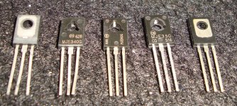
)about the offset KSE350 is the problem, but still not below 20mV
maybe must use good MJE340/350 because lot of them are fake here
MJE340 are fake but MJE350 look genuine
Thanks
Regards
Attachments
Last edited:
Thanks you Andrew Tpost1786
shows how to calculate Vpk from load and power specification.
Ok, now for 500W into 4R load
Vpk = sqrt(500 * 4 * 2)
= sqrt(4000)
Vpk = 63.2
Now I know to get 500W into 4R load we need 63.2 Vpk but
how I know the ideal rail voltage to get this 63.2 Vpk?
If the rail voltage says +80/-80V DC is this enough?
I know to get 63.2 Vpk we need higher rail but don't know how much high
also the Vac from trafo says 57Vac = 80VDC
in real life maybe not 80VDC, it's will drop anyway... bad caps or something else
I'm sorry if I miss the formula to calculate this rail voltage, if there was posted
Regards
Have you found the problem?Hi everyone,
Hi jacobsetti, have you built it one?
Mr Mile will be answer you if you built one of this good amp
Maybe 60 - 0 - 60 volt DC will give you 300w to 4R
see this one http://www.diyaudio.com/forums/solid-state/164093-100w-ultimate-fidelity-amplifier-92.html AX20
I made it, my B500
already on the heatsink & hope not too small
But:
1. Why offset just to high
as recommended 20mV or less, my B500 is
-466mV & -123mV
& the voltage
on 100ohm resistor is little below 0,5V
on base emitter KSE340(bias) is little below 2V
2. use 2 x transformer 50Vac but
DC after rectifier is 61VDC, should be 65-66VDC
(Vac is drop to 46Vac because test is at night)
Maybe bad caps or something?
Anyone please help, where do I start to check it out?
Regards
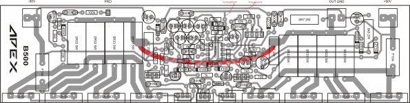
I'm sorry there was a mistake to my design...This is my new pcb design, change of 43k with 10k + 33k
another one is on page http://www.diyaudio.com/forums/solid-state/164208-500w-pa-amplifier-limiter-176.html
enjoy
pin of IC is split
pin 1 & pin 3
now there is two jumper on the back side of my PCB
that was make the amp not working...
I feel so sorry if there was anybody made it too
Now this couple amp I made has 8mV & 9mV offset
I will post picture soon
Regards
Yes I have...Have you found the problem?
Now it's working, but when the volume just a little the sound is distort
Maybe some bias adjust will fix this,
but I will experience with this
I want to otak atik
expect the quiescent voltage of a ClassAB amplifier to be ~1V below the Vpk at the smoothing capacitors.but
how I know the ideal rail voltage to get this 63.2 Vpk?
If the rail voltage says +80/-80V DC is this enough?
I know to get 63.2 Vpk we need higher rail but don't know how much high
also the Vac from trafo says 57Vac = 80VDC
in real life maybe not 80VDC, it's will drop anyway...
This will result in ~83V-1Vdc on the supply rail when the mains is at nominal voltage and the amplifier is biased to it's design settings.
Expect this 82Vdc rail voltage to vary by ~+-6% for mains supply variations. That will give you supply rail voltage range when delivering zero power of ~78Vdc to ~88Vdc.
Now to delivering maximum power.
Are you a manufacturer that is guaranteeing the maximum power at the output for the full range of possible mains voltages? Or a manufacturer looking to impress gullible customers where the guaranteed maximum power can only be delivered when mains supply is at maximum voltage tolerance?
Or a DIYer who wants Maximum Power when mains is at nominal supply voltage? Or do you want to design the output stage to survive the rare operational condition of maximum output power being delivered when mains supply voltage is at maximum tolerance?
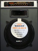
I don't wanna be a manufacturer looking to impress gullible customers
like that (like the picture bellow)
I don't want to lie or lying costumers like that
I have take a look what inside, there is one tafo 23,5Vac ct 23,5Vac (150VA maybe)
amplifier circuit using 1 pair TIP2955/3055 per channel
load 8 ohm
so the rail says +/-32 VDC
power output = ... I don't know how to calculate?
maybe only 50 to 60 watt, to get 50W need 28.2Vpk?
I am a DIYer who wants maximum power when my mains voltage allow to do maximum.
right here the ac main voltage not so good regulation
when at evening - night the voltage drop to 180V - 200V ac
normally its 220V ac
I don't have measuring equipment such as oscilloscope, but multitester only
So to get 500W to 4 R load = ... V DC? Please the formula or an example
Regards
Attachments
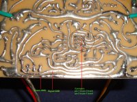
Yes mam...try to separate S ground and main ground
on your PCB main and s ground is joined it should be separated
mark red should be on separate wire going to ground of psu
It's just for testing amp...
The PCB track is separate
Few days ago I saw this Apexaudio Vertex Amp 2 Step - SOLFEGIO | www.solfegio.com
that is on Indonesian forum
Its really you (I don't think so) or someone else try to surprise the forum
I'm sorry if all of this make you mad
Thanks
Attachments
Last edited:
- Home
- Amplifiers
- Solid State
- 500W PA amplifier with Limiter