coolet,Coolet, thank You for this pcb design, can You help me to redesign pcbs of my old projects?
Regards
can you make quasi amp for beginner pcb smaller

coolet,
can you make quasi amp for beginner pcb smaller
I left space around VAS and drivers trasistors for TO220 heatsinks... U can find small pcb in thread http://www.diyaudio.com/forums/solid-state/164093-100w-ultimate-fidelity-amplifier-23.html post #230.
Regards
Last edited:
hi sir apex it is nesesary to put the step driver to b500?, f necessary would you please teach me or show me how it could be a possible connection to b500 and step driver..thanks and more power!!!
regards
jhun
No, I suggest to build B500 or if you want classH go to H900. Step driver with TL072 is for convert any classAB amp to classH, and it's share if IR2117 is not available.
Regards
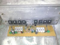
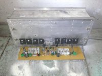
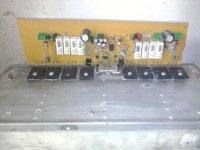
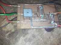
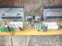
pics of my b500
hello sir pls help me out......
hello sir pls help me out......
Attachments
hello sir pls help me out......
I can't see is input GND connect to PSU GND (it's nessesery)? Do you measure voltage on suggested points?
im planning to build this amp...can i use a transformer with dual 32VAC @ 15Amps?..what major adjustment/s will I do?..can it still give 500w @ 4R?..pls help me..
With +/-45vdc use 1k/2W for R24,R25.
U can't get 500w @ 4R, not evan @ 2R, but U have realable and good sounding amp.
Regards
no....can i use a transformer with dual 32VAC @ 15Amps?..what major adjustment/s will I do?..can it still give 500w @ 4R?..pls help me..
32+32Vac could give about +-47Vdc at the supply rails.
This will allow approximately 37Vpk to a 4r0 load.
That is about 171W into 4r0, if you build this amplifier and PSU specifically to generate a high maximum power output.
If you bridge a pair of these amps you could maybe get 342W into 8r0, but there is no way to get 500W into 4r0 without bridging and building everything massively to achieve that power target.
For reference, 500W into 4r0 requires 63.2Vpk at the speaker terminals.
Vpk = sqrt(Power * Rload * 2).
Vac = sqrt(Power * Rload).
Few questions for you APEX
I am looking at the protection circuit
For the +-15V is 2 amps really necessary? It looks as this is only supply voltage for the opamp and the transistors.
I would also like to use 12Vmax not 24V for the fan. Is this an easy modification?
I am looking at the schematic but its hard to understand with the negative voltages. From what I gather the opamp gets a signal from the thermal diode then turns on the transistors to increase fan speed. I do not see a +12v for the fan. The -24V goes into the -12V regulator LM7912. From there it looks like the output -12V goes to the Fan+
Few questions for you APEX
I am looking at the protection circuit
For the +-15V is 2 amps really necessary? It looks as this is only supply voltage for the opamp and the transistors.
I would also like to use 12Vmax not 24V for the fan. Is this an easy modification?
I am looking at the schematic but its hard to understand with the negative voltages. From what I gather the opamp gets a signal from the thermal diode then turns on the transistors to increase fan speed. I do not see a +12v for the fan. The -24V goes into the -12V regulator LM7912. From there it looks like the output -12V goes to the Fan+
No need 2A, 500mA will be enough. U can use two 12V fans in seriers. Fan (+) is connect to GND, and (-) is on -12V (amp cold) -24V (amp hot). Reason to use 47R/5W is that in this case no need to use heatsink for LM7912.
Tnx for all the reply...how about dual 58Vac @ 25Amps?..can a single b500 produce sufficient power needed to drive 2x 500w 15" speaker with a horn tweeter?..pls help me out...
With 2x58vac/25A you can drive 2x15" per box.
APEX
Thank You for your input. I am learning alot from your designs. It is also helping me to remember my electronics better that I learned in school.
I have an interesting fan concept I would like to share. I will post soon.
If you understand my bad English, and short replys be welcome.
Regards
hello sir
i use same wiring as u told .
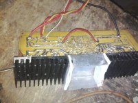
the temp is very high on heat sink where i fix the transistor.can u pls tell how much temp is good for that??
Disipation on heatsink at full power will be 150W for single channel B500 (AB class eficiency is 70%). Heatsink on your picture (B500 3 pairs output) is to small, without fan not enough for 100W amplifier. Do you measure BIAS.
Regards
- Home
- Amplifiers
- Solid State
- 500W PA amplifier with Limiter