In my opinion you should use this.
Regards
Is there any schematics for this protection (?) board?
Best regards!
I would like to help you, but I don`t have it. I only have the electronic diagram, you have to do it, it`s easy.
Regards
Regards
please kandimba attach the pcb files of the apex led light display for the front pannel
Is there any schematics for this protection (?) board?
Best regards!
I only have the pcb, but schematic are there.
Regards
B500P
yes sir but 500P has a balance input while i use ml3 in my tone control,
usually line and mic inputs/outputs we use here are unbalance,
any changes to make?
thanks
regards
In my opinion you should use this.
Regards
yes sir but 500P has a balance input while i use ml3 in my tone control,
usually line and mic inputs/outputs we use here are unbalance,
any changes to make?
thanks
regards
yes sir but 500P has a balance input while i use ml3 in my tone control,
usually line and mic inputs/outputs we use here are unbalance,
any changes to make?
thanks
regards
You can convert balanced input to unbalanced... just connect - input to gnd.
please kandimba attach the pcb files of the apex led light display for the front pannel
Hi Stewin, dont be sad because I did something for you
") . I hope that wil be useful.
. I hope that wil be useful.Regards
Attachments
Hi Stewin, dont be sad because I did something for you
Regards
You should teste it, because is not tested.
Regards
ML1, MX1, PSU
hi sir APEX sir and others
im planning to have a little mixer using
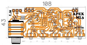
ML3
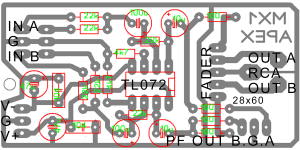
MX1
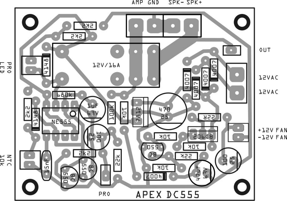
and this PSU i have changed the zener into 15V is this posible?
these are the only components i able to purchase.
i suppose to do the A Class PSU but not all devices are available esp BF245/2sk246 even the 1uf MKT/MYLAR caps, only electrolytic are available so i tried this layout but need your advice..
currently i am using ML3 on my AMPs with 7815 & 7915 still excellent performance than my tone from esp and sam.
i am not an electronics guy just a hobbyst
please help me out
thank you..
regards...
hi sir APEX sir and others
im planning to have a little mixer using
ML3
MX1
and this PSU i have changed the zener into 15V is this posible?
these are the only components i able to purchase.
i suppose to do the A Class PSU but not all devices are available esp BF245/2sk246 even the 1uf MKT/MYLAR caps, only electrolytic are available so i tried this layout but need your advice..
currently i am using ML3 on my AMPs with 7815 & 7915 still excellent performance than my tone from esp and sam.
i am not an electronics guy just a hobbyst
please help me out
thank you..
regards...
Attachments
you still don't get the point.
I advocate protection.
I suggest the Triac shorting circuit be moved from output to supply rails.
I am not telling anyone to remove protection. That is completely against my philosophy.
I stumbled across this old post, which i find very interesting as an idea. Why blow the heck out of an output stage, when you can stop the failure in front of it in a safer way?
My question is, how would this be utilized? Two triacs, each across the + and - rail and ground, fired by the same diac? Or maybe one triac across the full rails? Any ideas?
Hi Stewin, dont be sad because I did something for you
Regards
thanks kandimba . here is my version also smd version and dip version
Attachments
-
autorange apex vu meter schematic.pdf13.2 KB · Views: 369
-
autorange apex vu meter components full.pdf18.9 KB · Views: 343
-
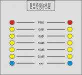 APEX VU dB.JPG45.2 KB · Views: 966
 -
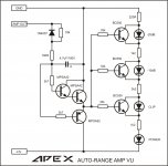 APEX Amp VU.jpg172.3 KB · Views: 991
 -
gtG front panel standard top components full.pdf15.7 KB · Views: 283
-
gtG front panel standard schematic.pdf13.5 KB · Views: 304
-
gtG front panel standard pcb bottom.pdf7.9 KB · Views: 307
-
gtG front panel standard bottom components full.pdf7.1 KB · Views: 360
-
autorange apex vu meter pcb bottom.pdf6.9 KB · Views: 319
-
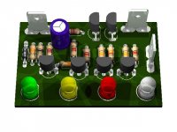 autorange apex vu meter.jpg83.8 KB · Views: 949
What if we use one triac (or thyristor,mosfet whatever) from + to - rail, -rail go short, there's 50/50 chance that - fuse will blow. If bad luck strikes and + rail blow, there is still dc from - rail. Is it?
So i guess that each rail should be treated separetely, each fitted with its own triac to ground. Should be safer that way, as both triacs will be driven by the same diac and so in a case of a fault, both rail fuses will die at the same time.
... as both triacs will be driven by the same diac ...
Does this really work?
As said before, I'd use SCRs that don't need to be triggered by a DIAC.
Best regards!
An externally hosted image should be here but it was not working when we last tested it.
Does this really work?
I really hope so!
Maybe C1 should be a little bigger, like 2.2μF and of course R1 a little lower, like 150k.
I insist on triacs because they are a lot cheaper than a proper SCR!
Last edited:
I thought you'd need one DIAC per device?
Yea, that should be the proper way. Problem is that DIACs are very inacutate devices, as their breakdown voltage ranges from 28 to 36 volts! So i fear that two discrete DIACs might not fire simultaneously, should they ever hear the call of duty! But i might be wrong! Probably i am
What if we use one triac (or thyristor,mosfet whatever) from + to - rail, -rail go short, there's 50/50 chance that - fuse will blow. If bad luck strikes and + rail blow, there is still dc from - rail. Is it?
Just check out the Mackie M1400 schematic! The first version use thyristors as crowbar in the power supply. Thyristors are very rugged, and they are specified for fuse blowing.
Sajti
- Home
- Amplifiers
- Solid State
- 500W PA amplifier with Limiter