70Vpk (from +-80Vdc supplies) into 2r0 resistor test load is equivalent to 35Apk.
Please note the rail sagging. The Mackie amp has the following specification:
300W/8ohm approx.70Vpeak
500W/4ohm approx. 63Vpeak
700W/2ohm approx. 53Vpeak
This means about 26A peak output. Peak output current can be 39-130A. Count with the 20A/output device the gain of the MJL21193/4 is minimum gain about 10. This gives 8A totalbace current. The driver has the gain about 30, which menas 270mA base current for the driver. It's not impossible, I guess.
Anyway the overcurrent protection should trigger earlier...
Sajti
70Vpk (from +-80Vdc supplies) into 2r0 resistor test load is equivalent to 35Apk.
When driving a reactive speaker load the current demand on transients can be anywhere from 150% to 500% of the resistive test current.
Expect peak transient currents of 52.5Apk to 175Apk
A 4pair output stage will have to pass upto 20Apk regularly through each output device.
One needs to look at the transistor gain for 20Apk and determine the peak transient base current.
Then work through the stages to determine the pre-driver and VAS peak currents.
Working in ClassG & H does not provide any solution for this peak current demand made by reactive speakers.
sir I m talking about the TEF version of APEX B500 which has 7 pair output transistors,,.
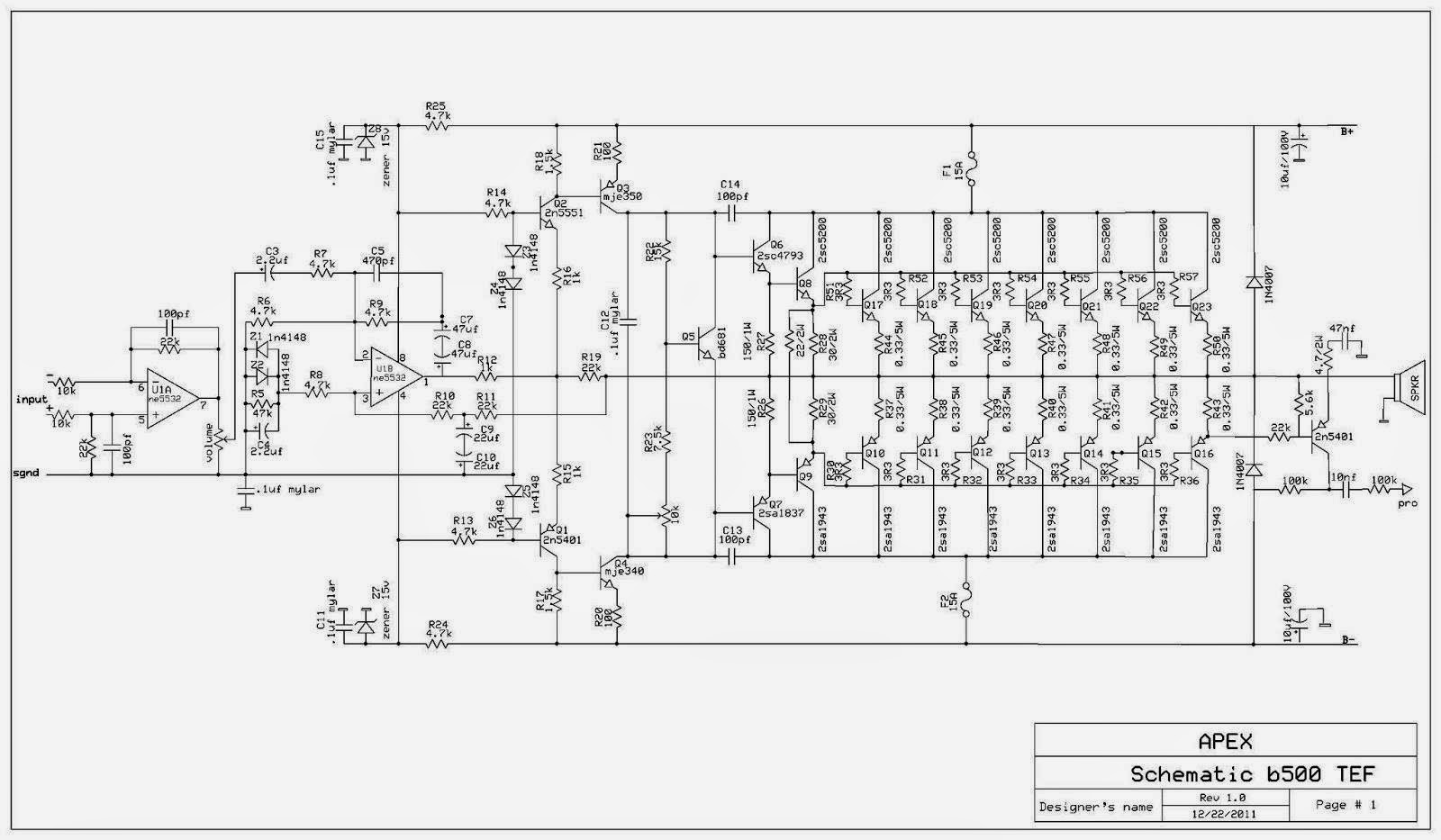
.and I want to use 50 v ac i.e 70v dc...and yes it is not possible to connect a 2 ohms speaker ...it burns everything...thank u for ur valuable answer....I just built it for 500watt rms PA amplifier..in 4 ohms speaker..
4r0 is different from 2r0 and different from 2ohms and different from 4ohms.
One must decide what speaker needs to be driven.
Then design the output stages to drive that reactive impedance.
One does not look at a possible project and just guess at what speaker impedance could be used.
It is a DESIGN exercise.
One must decide what speaker needs to be driven.
Then design the output stages to drive that reactive impedance.
One does not look at a possible project and just guess at what speaker impedance could be used.
It is a DESIGN exercise.
4r0 is different from 2r0 and different from 2ohms and different from 4ohms.
One must decide what speaker needs to be driven.
Then design the output stages to drive that reactive impedance.
One does not look at a possible project and just guess at what speaker impedance could be used.
It is a DESIGN exercise.
sir,look at this design.
this is famous Rod Elliot subwoofer amplifier...out put is 150w in 8 ohms load..input rail +-56 volt.
and look at the image.
2 pair extra output transistor....gives 240w in 4 ohms load....but..here driver stage is very powerful...thats very important....
 .
.
Last edited by a moderator:
sir,look at this design.
![B]](/community/proxy.php?image=http%3A%2F%2F%5BB%5DCopyright+image+removed+by+moderation%5B%2FB%5D&hash=2c4bc3434055f1d7586291f6dde7674a)
this is famous Rod Elliot subwoofer amplifier...out put is 150w in 8 ohms load..input rail +-56 volt.
and look at the image.
2 pair extra output transistor....gives 240w in 4 ohms load....but..here driver stage is very powerful...thats very important....

Please read the notes toward the end of this page,
Elliott Sound Products - The Audio Pages (Main Index)
In particular "Links"
Please read the notes toward the end of this page,
Elliott Sound Products - The Audio Pages (Main Index)
In particular "Links"
i am very sorry..i did not know the copyright rule of esp..very sorry for that..
I'm so confused, about the posting of esp pictures.
It's ONLY esp that I'm aware of that protests like this.
But the site and it's members have the utmost respect for Mr Elliot, so I guess we'll jump through the hoops required.
Maybe its just easier not to link/refer to his pages at all.
The he will never get traffic from this site to his.
It's ONLY esp that I'm aware of that protests like this.
But the site and it's members have the utmost respect for Mr Elliot, so I guess we'll jump through the hoops required.
Maybe its just easier not to link/refer to his pages at all.
The he will never get traffic from this site to his.
Hello to all
please
can anyone tell that
I want to use b500 tef with 2x60vac trafo on 2 ohms
its a must need for me because i want it be more than stable on 4 ohms
please tell me the no of output tranees to be used as i have plenty of 2sc5200 pairs and transformer ratings
please
can anyone tell that
I want to use b500 tef with 2x60vac trafo on 2 ohms
its a must need for me because i want it be more than stable on 4 ohms
please tell me the no of output tranees to be used as i have plenty of 2sc5200 pairs and transformer ratings
If you have a 4ohms speaker then you design the amplifier to drive a 4ohms load.
One criteria I use is that the amplifier MUST BE ABLE to drive a resistor test load that is half the nominal speaker impedance. This is not a stability requirement. It's about current capability into reactive loads.
I now design to drive 1/3rd nominal load resistance for a very short period. Just long enough to see the sinewave on the scope. This would be the equivalent to driving a 1r3 test resistor for a 4ohms amplifier.
The total Pmax of the output devices should be ~ F times the maximum power output of the amplifier.
F = 4 for mosFET devices
F = 5 to 6 for BJT devices.
eg using 2pair of 250W devices (MJ15003/4) total Pmax = 4 * 250W = 1000W
For BJTs F= 5 to 6.
Max Power = 1000 / 5 = 200W
This depends very much on the temperature de-rated SOA of the devices and the temperature of the heatsink that you will typically use, as well as how severe the speaker is in stressing the output stage.
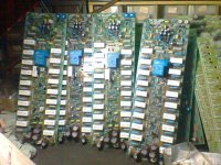
new design apex b500tef...work..tanks apex audio
and h900tef on trial.
and h900tef on trial.
Attachments
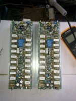
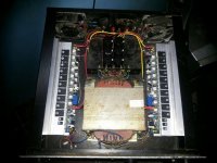
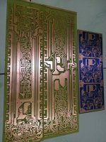
new design apex b500tef...work..tanks apex audio
and h900tef on trial.
Nice work,
Regards
- Home
- Amplifiers
- Solid State
- 500W PA amplifier with Limiter