I'm having a problem simulating the protection circuit in this design. I've setup the basic Low TIM Leach current limiter, and when I drive the amp hard (1.5Vp-p, 1Khz into 0.8R) the negative half of the output waveform completely clips at ~31V(~19.4A) where as the positive half of the waveform looks only slightly rounded and reaches ~34V(21.4A). The negative waveform has an oscillation spike on the rising edge.
Ib of the protection resistors shows some of the story. The negative side waveform clips at -21uA whereas the positive side reaches 120uA cleanly.
I've gone back through the circuit half a dozen times and haven't found any errors. I've switched models for the protection transistor pair and the output transistors with no change. I even completely deleted all the protection circuitry and re-drew it with no change.
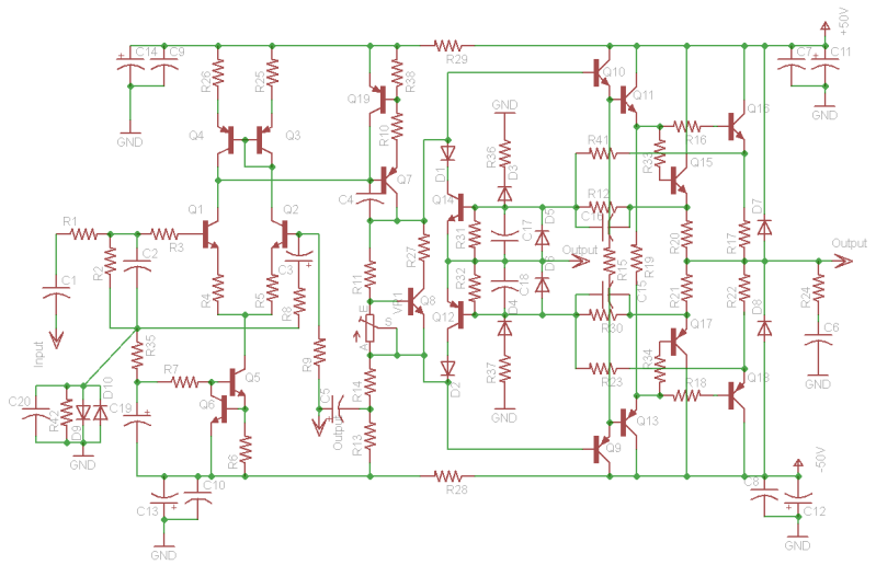
I'm working with the triple EF equivalent circuit now (schematic below)...
Any ideas here? I really don't see how this can be normal operation.
Ib of the protection resistors shows some of the story. The negative side waveform clips at -21uA whereas the positive side reaches 120uA cleanly.
I've gone back through the circuit half a dozen times and haven't found any errors. I've switched models for the protection transistor pair and the output transistors with no change. I even completely deleted all the protection circuitry and re-drew it with no change.
I'm working with the triple EF equivalent circuit now (schematic below)...
Any ideas here? I really don't see how this can be normal operation.
disable the protection in the simulator. Check again. You may have to disable the protection around the VAS.
The Leach protection locus is a two slope current limiter. It needs and extra resistor to become a two slope IV limiter.
The limiting trigger points are VERY dependent on the Vbe of the shorting transistor. Slight variations in the sim models could easily account for different limits in the opposite polarities.
Last edited:
Sorry for the long times in between posts here, haven't had to much time to work with this.
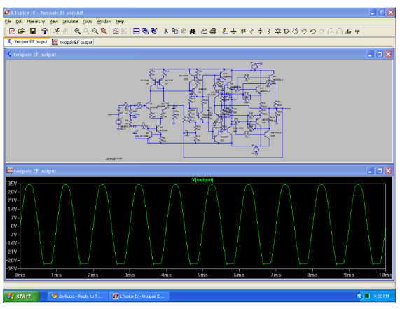
I disabled the protection by disconnecting the sense resistors and the output wave becomes relatively clean, no clipping.
I've tried a few differant pnp's using other ltspice models, On semi models, and others, for the protection transistor on the negative side. Same results.
I plan on using a VI limiter arrangement, just trying to understand this first.
Hi,
if the amplifier simulations are now all OK and meet your targets, then start reading up on I limiting and VI limiting and single slope and dual slope and multi-slope.
Understand the difference between the need for DC condition limiting and why transient signals must be allowed to pass that are much much higher than the DC limits. Find out how to limit these transients, both very short and medium term while still meeting the DC limits using circuits that can differentiate between fast and slow signals.
Then try to design you VI limiter to meet whatever targets you have set to protect the amplifier ( and the speaker) while still passing all valid audio signals to all valid audio loads.
- Status
- This old topic is closed. If you want to reopen this topic, contact a moderator using the "Report Post" button.