There's some good info here on advantages and disadvantages of various transistors for VAS.
http://www.diyaudio.com/forums/solid-state/112227-about-vas-drivers-transistors-6.html
http://www.diyaudio.com/forums/solid-state/112227-about-vas-drivers-transistors-6.html
Bimo, can you clarify. Are you saying the 2SC3503/KSC3503 is a drop in replacement for the BC639/BC640, that will also perform better?
The power ratings are much different. Especially considering the FX8 max V is +/-40V.
In simulation it will perform better, but of course you should try yourself. "Perform better" is not necessary "sound better". Because people have different taste. Some people prefer high distortion
Thick film SMD are metal oxide. These generally have a 300ppm/C tempco.
Metal film which are generally used for through hole have an equivalent in smd, Thin Film. These generally have a 25 to 100ppm/C
If you know your resistor has a very narrow temperature operating range from cold to fully warmed up then 25ppm/C rarely offers any benefit over 100ppm/C in audio. There are exceptions.
But 300ppm/C can introduce small errors that are audible and measureable.
An example is the Feedback resistor in the upper leg of the Amplifier NFB loop.
The feedback loop can have the peak transient voltage across it, a 100W into 8ohms amp gives peak output approaching 41Vpk to 42Vpk.
Apply this across a 20K:680r feedback loop and the instantaneous current is 2.031mApk
That gives an instantaneous power dissipation in the two resistors of 82.5mW and 2.8mW
The two resistors do not maintain the same ratio as they warm up and cool down. That is distortion of the output and it gets worse the higher the tempco.
Id be curious if you could figure out what Toshiba cob parts would perform better then the BC639/640 in there perspective positions and be a drop in replacement.
Small signal transistors in TO92 casings usually have very high ft and very low Cob. If current demand is not too high, there is very good reason to use TO92 transistors for VAS duty.
A gift from me. Not tested!
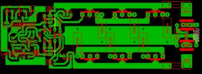
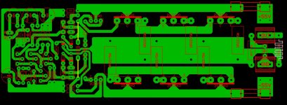
So you picked 2SA1381 / 2SC3503. Nice PCB layout too. Don't you think Q7,Q8 should be on the edge of the PCB for a sink?
Last edited:
So you picked 2SA1381 / 2SC3503. Nice PCB layout too. Don't you think Q7,Q8 should be on the edge of the PCB for a sink?
There are quite a few varieties of physical layouts that will accommodate attachment of heatsink. This one appears to be the mounting of Q7 and Q8 to the bottom of the board allowing the screw to be tightened where the device peeks out of the left and right sides. This gives the devices a larger physical separation, and to my mind, better heat dissipation, at the cost of perhaps a less-convenient overall chassis design? I like this arrangement. Can't articulate it better. Might just be superstition.
I have only given this a quick glance, however... Should the heavy, flat line representing the back of the device be on the other side - i.e. are the devices rotated 180 degrees? Sorry, if I am mistaken. Alternatively, I have seen a few designs that actually run wires from the MOSFETs to the heatsink, apparently as much as 6-8 inches - not recommending it, but it's been done.
Last edited:
So you picked 2SA1381 / 2SC3503. Nice PCB layout too. Don't you think Q7,Q8 should be on the edge of the PCB for a sink?
Q7 dan Q8 mounted below PCB to heatsink
A gift from me. Not tested!
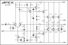
C1 and C8 = MKP.
C2, C5, C10, and C11 = Ceramic NP0 or Silver Mica.
R11 and R12 should be high quality metal film.
Q1 and Q3 should be match and tie (thermally coupled) for lower DC offset and stability from temperature.
Q7 dan Q8 mounted below PCB to heatsink
I think that it is the most practical method for mounting of output transistors.
A gift from me. Not tested!
Hi bimo nice layout. Could one also add anti parallel diodes for gnd lift?
No local supply decoupling.
NFB tapped off wrong end of the output rail.
Output Zobel return route not connected to amplifier output devices.
Drivers have lots of capacity for far more than a 2pair output stage.
Output stage of 2pair of 1943/5200 cannot drive 150W into 8ohms reliably from your ±55Vdc supply rails.
Three pair would work. And use smaller, faster drivers. Try mje15034/5
No base stoppers for the drivers, nor the outputs.
Ask Apex what happens if ONE supply rail fuse opens.
Ask Apex how well the lack of bias tempco works.
Last edited:
A gift from me. Not tested!
Thank you - looks really good. Can you please provide Gerber files for fabrication by a PCB shop?
Here is my latest. TINA file attached.
Hi egra,
how is bias set in your schema of fx-8
reg
prasi
OK now i see its already answered in later post.
Last edited:
Second amplifier fully cased, this time Mr. Apex AX10:
http://www.upload.ee/image/5734722/160420161883.jpg
http://www.upload.ee/image/5734723/160420161884.jpg
http://www.upload.ee/image/5734726/160420161885.jpg
http://www.upload.ee/image/5734728/160420161886.jpg
2SC5200 paired with Tips as drivers. BD138 and 137 as VAS, BC550C LPT and MPSA06 as CSS. Tips base resistor 94R, Toshiba base resistor 1R, that way it is sounding good.
Potentiometer is instead 220R resistor on CSS emitter. Potentiometer value set to 340R.
Output bias current 20mA per device, measured on 10R resistor.
VAS current ~2.5mA, measured on 47R emitter resistors.
LTP current is around 1mA
Feedback cap is 100uF some nichicon audio grade. Input cap is 10uF.
I like it that way, i have tried to push a lot bias current through output devices and the sound becomes not quite understandable...i like when there is separation... most of us know what i mean.
I have tried 220uF ultra low ESR cap @ feedback and the result was awful.
Strong middle..(drums), nice high's, cool sound @ low bias.
Bass is good but not the best, .. maybe its the u101 transformer... being too low value cuz on naim clone with 500VA transformer i don't only got deep bass but its more like controlled "rhythmic" too
As Apex suggested, i paired it with Texas.
In some pics you will see Texas(opa2134x2) as 0.1x gain preamp without regulators, just filter bank powered.
There is also a fully passive switch. Trough it you are able to switch between direct input and Texas, this is my first A/B system built in amplifier.
So far i am not able to hear difference between direct computer sound card or when listening trough Texas, it mimics the input sound without any loss. Switching speed is in millisecond
In overall, compared to Naim Clone or Sony RX55, this AX10 is a totally different beast... very huge difference in the background/soundstage. No matter what i did to Naim Clones, i never got as good soundstage as with AX10.
About very low frequency's, there is surely some damping factor involved... it could be just my speaker too(boomy with some amplifiers) or the room/speaker combination itself. Maybe i left my huge door open and that changed the frequency response...
PSU 0V is grounded/tied with metal case.
Last edited:
Second amplifier fully cased, this time Mr. Apex AX10:
http://www.upload.ee/image/5734722/160420161883.jpg
http://www.upload.ee/image/5734723/160420161884.jpg
http://www.upload.ee/image/5734726/160420161885.jpg
http://www.upload.ee/image/5734728/160420161886.jpg
2SC5200 paired with Tips as drivers. BD138 and 137 as VAS, BC550C LPT and MPSA06 as CSS. Tips base resistor 94R, Toshiba base resistor 1R, that way it is sounding good.
Potentiometer is instead 220R resistor on CSS emitter. Potentiometer value set to 340R.
Output bias current 20mA per device, measured on 10R resistor.
VAS current ~2.5mA, measured on 47R emitter resistors.
LTP current is around 1mA
Feedback cap is 100uF some nichicon audio grade. Input cap is 10uF.
I like it that way, i have tried to push a lot bias current through output devices and the sound becomes not quite understandable...i like when there is separation... most of us know what i mean.
I have tried 220uF ultra low ESR cap @ feedback and the result was awful.
Strong middle..(drums), nice high's, cool sound @ low bias.
Bass is good but not the best, .. maybe its the u101 transformer... being too low value cuz on naim clone with 500VA transformer i don't only got deep bass but its more like controlled "rhythmic" too
As Apex suggested, i paired it with Texas.
In some pics you will see Texas(opa2134x2) as 0.1x gain preamp without regulators, just filter bank powered.
There is also a fully passive switch. Trough it you are able to switch between direct input and Texas, this is my first A/B system built in amplifier.
So far i am not able to hear difference between direct computer sound card or when listening trough Texas, it mimics the input sound without any loss. Switching speed is in millisecond
In overall, compared to Naim Clone or Sony RX55, this AX10 is a totally different beast... very huge difference in the background/soundstage. No matter what i did to Naim Clones, i never got as good soundstage as with AX10.
About very low frequency's, there is surely some damping factor involved... it could be just my speaker too(boomy with some amplifiers) or the room/speaker combination itself. Maybe i left my huge door open and that changed the frequency response...
PSU 0V is grounded/tied with metal case.
hello sir try to use the image attaching from diyAudio webpage the link you post of your images maybe in the future, might be lost also try to keep images in small size there is guide of how many kilobytes are allowed but don't make them too small, in case you need help for troubleshooting a circuit they are good eyes here that always help for sure
Regards
Juan
Attachments
- Home
- Amplifiers
- Solid State
- 100W Ultimate Fidelity Amplifier


