Hi already replaced all the bcs and 5401 transistor but still have 7volts dc offset. Pls help
I suspect grounding scheme. Tell us where all input and output grounds originate and terminate.
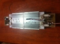
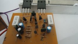
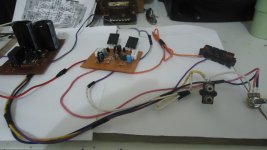
my ax-11 build.
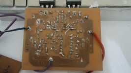
a little bit of a challenge putting the TO-3 trans to the heat sink.
careful must be taken not to create a short circuit between the heat sink and the TO-3 collectors.
i used Teflon tape to insulate the bolts from touching the heat sink holes.
i replaced driver parts as follows:
MJE340/350 ---> 2SC4793/2SA1837
MJE15034/35 ---> MJE15032/33
MPSA13 ---> BD679
and used +/-50vdc rail, and output trans MJ15015/16.
DC offset is about 110mV.
there is no quiescent current across output 0R22 resistors, and BD679.
the sound is low and rough at high volume.
any idea what needs to be adjusted?
edit: Cjkpkg has paralleled the 3.3k with 15k to get 2.7k, i think i will try this setting.
Attachments
Last edited:
my ax-11 build.
a little bit of a challenge putting the TO-3 trans to the heat sink.
careful must be taken not to create a short circuit between the heat sink and the TO-3 collectors.
i used Teflon tape to insulate the bolts from touching the heat sink holes.
i replaced driver parts as follows:
MJE340/350 ---> 2SC4793/2SA1837
MJE15034/35 ---> MJE15032/33
MPSA13 ---> BD679
and used +/-50vdc rail, and output trans MJ15015/16.
DC offset is about 110mV.
there is no quiescent current across output 0R22 resistors, and BD679.
the sound is low and rough at high volume.
any idea what needs to be adjusted?
edit: Cjkpkg has paralleled the 3.3k with 15k to get 2.7k, i think i will try this setting.
Yes I had a devil of a time keeping the TO-3's isolated. I greatly oversized the holes in my "L" profile and had to spend a lot of time smoothing the surface so when screwed down they did not make contact through the sil-pads.
Also, I ended up paralleling 100K multi turn pots across the 3K3 resistors, apparently my transistors are not very well matched across the 2 pairs.
I made some small changes to ax11 amp - as sansui au217 amplifier (preaty same amp) and have smmall question - can the input buffer be bypassed and input pair be substituted with 2sk170 tranies ?
I have made some simulations and amp is preatty quick and looks stable.
The square is 20kHz
THX
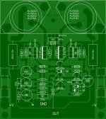
Yes borys, you can use j-fet input, put some base stopers at o/p transistors, reduce compensation in vas and put small compensation in driver stage. Then You should have SR around 40-50V/us and good THD results at high range.
Reduce VAS stage bias to 7mA (no need heatsink) and increase bias for driver stage to aprox 15-20mA (should swing in A class). There should be no overshoot and amp remain perfect stable.
Basicly it should look like this.
Regards
Attachments
Nice borys... How's the sound impression using j-fet input?Yes borys, you can use j-fet input, put some base stopers at o/p transistors, reduce compensation in vas and put small compensation in driver stage. Then You should have SR around 40-50V/us and good THD results at high range.
Reduce VAS stage bias to 7mA (no need heatsink) and increase bias for driver stage to aprox 15-20mA (should swing in A class). There should be no overshoot and amp remain perfect stable.
Basicly it should look like this.
Regards
Can you post the files i'd like to give a try.
pcb looks pretty small...
Regards,
Last edited:
Yes borys, you can use j-fet input, put some base stopers at o/p transistors, reduce compensation in vas and put small compensation in driver stage. Then You should have SR around 40-50V/us and good THD results at high range.
Reduce VAS stage bias to 7mA (no need heatsink) and increase bias for driver stage to aprox 15-20mA (should swing in A class). There should be no overshoot and amp remain perfect stable.
Basicly it should look like this.
Regards
Nice work, I use 2SK117 in my HD series amp with 3mA bias per j-fet and diamond differential VAS.
Regards
Nice work, I use 2SK117 in my HD series amp with 3mA bias per j-fet and diamond differential VAS.
Regards
Would You know any j-fet siutable for 50V ?
I will try higher bias for j-fet too.
Regards
Would You know any j-fet siutable for 50V ?
I will try higher bias for j-fet too.
Regards
I suggest to cascode j-fets or use 24V zeners.
Nice work, I use 2SK117 in my HD series amp with 3mA bias per j-fet and diamond differential VAS.
Regards
Sound interesting....
")
Mr. Mile would that HD series preparation includes AX11 and AX-14?
Regards,
wiljj78
Bellow You have packet with bit modyfiet board.
Just replace bc546 at the input with 2sk170 (do not go over +/-40V with fets).
Many thanks borys.... and Yes i will try this with +/-38vdc max.
Regards,
ax-11 need help
i pulled out transistors except the bc546 and mpsa92. tested them and they are all good.put them back and measured their voltages.
2sc5200 2sa1943 bd139 bd140 2sa2383 2sc1013
vbc-13.49v vbc-0.7v vbc-8.95v vbc-395mv vbc-200mv vbc-8.69v
vbe-0.2v vbe-0.2v vbe-16mv vbe-15mv vbe-215mv vbe-42mv
vce-16.9v vec-11.9v vce-12.7v vce-655mv vce-190mv vce-8.79v
mpsa13 vce-0v and amp out is 13.5v
all ground have individual wire come from psu ground. can i know what was the trouble of this ax-11 pcb?
thank you
joeyt
Attachments
2sc5200 -vbc13.49v/ vbe- 0.2v /vce-16.9v
2sa1843-vbc 0.7v/ vbe-0.20v /vce-11-9v
bd139 vbc-8.9v /vbe16mv /vce-12.7v
bd140 vbc-395mv /vbe-15mv /vce-655mv
2sa2383 vbc-200mv / vbe-215mv / vce-190mv
2sc1013 vbc-8.69v / vbe-42mv /vce-8.79v
this is a correction from my last posted.
thanks
joeyt
2sa1843-vbc 0.7v/ vbe-0.20v /vce-11-9v
bd139 vbc-8.9v /vbe16mv /vce-12.7v
bd140 vbc-395mv /vbe-15mv /vce-655mv
2sa2383 vbc-200mv / vbe-215mv / vce-190mv
2sc1013 vbc-8.69v / vbe-42mv /vce-8.79v
this is a correction from my last posted.
thanks
joeyt
2sc5200 -vbc13.49v/ vbe- 0.2v /vce-16.9v
2sa1843-vbc 0.7v/ vbe-0.20v /vce-11-9v
bd139 vbc-8.9v /vbe16mv /vce-12.7v
bd140 vbc-395mv /vbe-15mv /vce-655mv
2sa2383 vbc-200mv / vbe-215mv / vce-190mv
2sc1013 vbc-8.69v / vbe-42mv /vce-8.79v
this is a correction from my last posted.
thanks
joeyt
What about voltages on BC546 and MPSA92?
What about voltages on BC546 and MPSA92?
bc546 collector connected to base of mpsa92
vbe-0.36v /vbc-27.8v /vce-25.9v
vbe-606mv /vbc-16.8v /vce-18v- after 10 mins.
bc546 base connected to 330pf
vbe-4.8v/ vbc-34.4v /vce-26,3v
vbe-8v /vbc26.5v /vce18.8v -after 10 mins.
bc546 base connected to - pin of in4148
vbe-4.81v /vbc-15.46/ vce-10.78v
mpsa92
vbe-565mv /vbc-30v /vce-30v - same v measurement after 10 mins.
- Home
- Amplifiers
- Solid State
- 100W Ultimate Fidelity Amplifier