Hi everyone.
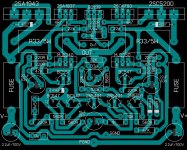
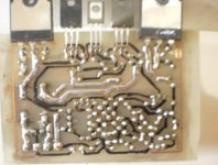
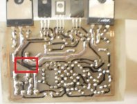
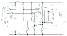
I have just completed drawing my own PCB based on the symmetrical design that has been already posted here. This PCB design has wider tracks.
Please, if someone can check whether there are any errors in it. If everything is OK, than I will share the files in PDF format, so everyone can use them.
Thanks.
Attachments
Mr.Mile, this is my ax14. the problem is still the same as the time it C.without input connection, and then immediately turned ax14 cried like horn, huuumm, and noisy.
I also tried to remove the capacitor 100nF then I replace it with a jumper, but the result is still the same. please correct my mistake

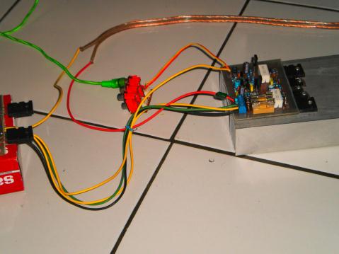

sorry for english
I also tried to remove the capacitor 100nF then I replace it with a jumper, but the result is still the same. please correct my mistake
sorry for english
Attachments
Mr.Mile, this is my ax14. the problem is still the same as the time it C.without input connection, and then immediately turned ax14 cried like horn, huuumm, and noisy.
I also tried to remove the capacitor 100nF then I replace it with a jumper, but the result is still the same. please correct my mistake
sorry for english
Please sketch out your grounding scheme.
What worked for me was rca input ground to amp board
Input ground to chassis star ground
Amp board ground to PSU ground
Speaker ground to PSU ground
I did try the third suggested wire from input ground to PSU ground but found the amp to be most quiet without that connection.
My experience was connect input rca ground into PSU ground fixed my systems' problem...before you hook your amp to your speaker, please measure the dc offset first..Try to post clear pictures and measurements (rail voltage,DC offset, etc) it will be more easy to all diy freinds to help...
Regards,
state here your dc offset first...what rail voltage do you have?
Best Regards
Arif B
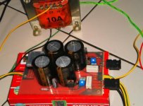
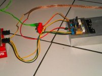
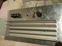
Apex B80 as a car amp with an SMPS
Thank you Mile for the simple and powerful design! good enough for a 10" woofer. Next step is D200.with +/- 75v supply and with low Rds drivers")
Thank you Mile for the simple and powerful design! good enough for a 10" woofer. Next step is D200.with +/- 75v supply and with low Rds drivers
Attachments
Thank you Mile for the simple and powerful design! good enough for a 10" woofer. Next step is D200.with +/- 75v supply and with low Rds drivers
Nice work,
Regards
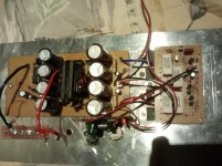
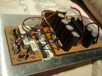
you will have a lot of power with d-class amp that´s for sure! what power is that smps? it look´s really simple...
Yes. Its a very simple smps driven 2 FETs by SG3525.
No input and output filters.
I followed a couple of DIY projects and requested my friend to design a PCB for me
It runs at 50Khz
The transformer ETD39, I wound it myself. Hope it can produce about 200W.
voltage regulated for +/- 35
Cheers!
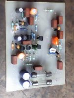
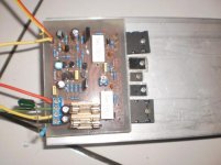
This is, the simple 100W amplifier.
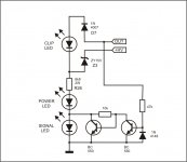
Ultra low distortion (0.0005%). Beautiful sign, the border is reached (clipp). The output power transistors can not be opened ever crossed. The current level is not increased if there are fast and clipp signals simultaneously. The operational amplifier strengthens the useful signal to 0 dB, the error signals are amplified 30 dB. Final result, the error signals are reduced more than 20dB. Built-in protection work if over 10A
Ultra low distortion (0.0005%). Beautiful sign, the border is reached (clipp). The output power transistors can not be opened ever crossed. The current level is not increased if there are fast and clipp signals simultaneously. The operational amplifier strengthens the useful signal to 0 dB, the error signals are amplified 30 dB. Final result, the error signals are reduced more than 20dB. Built-in protection work if over 10A
Attachments
This is, the simple 100W amplifier.
Ultra low distortion (0.0005%). Beautiful sign, the border is reached (clipp). The output power transistors can not be opened ever crossed. The current level is not increased if there are fast and clipp signals simultaneously. The operational amplifier strengthens the useful signal to 0 dB, the error signals are amplified 30 dB. Final result, the error signals are reduced more than 20dB. Built-in protection work if over 10A
why not in new thread? any pcb,pictures of finished amp or even video perhaps?
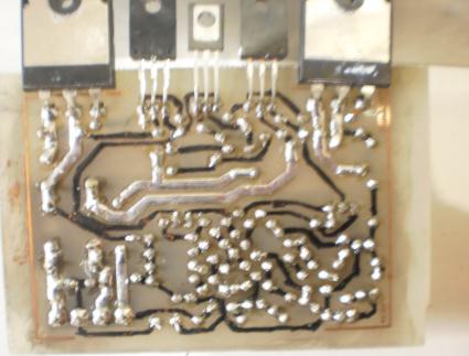
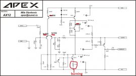
Resistor 47ohm burned
Greetings all ... this my first post ...
I tried to assemble B80/ax12 by modifying of PCB ocl150 old.
when turned on, 47ohm resistor on the emitter transistor 2n5551 fire continues, but the transistor was not burned.
what makes a resistor 47 fire hold?
please help.......
sorry about my English poor
thanks
Attachments
hiGreetings all ... this my first post ...
I tried to assemble B80/ax12 by modifying of PCB ocl150 old.
when turned on, 47ohm resistor on the emitter transistor 2n5551 fire continues, but the transistor was not burned.
what makes a resistor 47 fire hold?
please help.......
sorry about my English poor
thanks
i was used this amp in my car.
this amp work well
it worked in first time
chek your teransistors pin
hi
i was used this amp in my car.
this amp work well
it worked in first time
chek your teransistors pin
thank you sir for your advice
i was check transistor 2n5551 pin, it's right. i check the other Tr, I check tr bc556 pin, the pin is rotated between the emitter and the Tr colector and two damaged. I've replaced it and tried to turn on, the resistor is not burning anymore.
once again thank you sir.
- Home
- Amplifiers
- Solid State
- 100W Ultimate Fidelity Amplifier