Hi..Apex..for Nx14v2..can I used Tr 2SA1668/2SC4382 instead SA1837/SC4793 for driver??
Pozdrav..
2SA1668/2SC4382 can be used for drivers in any version of 'Ulti-Fi' amp.
Pozdrav
Thanks Apex...I will built it.
Regards
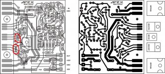
Use 10R in parallel with C13(100nF) for test or GND wirwing circuit as I suggest for all my amps (GND from PSU to input terminal),
Regards
Miles,
I have many IRFP452 (TO-3 metalcan) by samsung. Can this be used here?
They are from old PSU.
Thanks.
You probably have IRF452 in TO-3 case, IRFP452 is in TO-247 case like IRFP250. Any of this MOSFETs can be used for NX14 amp.
Regards
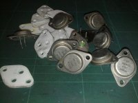
You are right Miles. IRF452 is the one. So it can be used!
Thanks.
There is IRF450 and it can be used also. MOSFETs are from IR not from SAMSUNG.
Regards
There is IRF450 and it can be used also. MOSFETs are from IR not from SAMSUNG.
Regards
Yeah I was looking on the net for datasheet and samsung comes out??
But anyway I will try this NX14.
Raj.
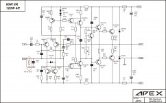
APEX AX-14 (modifications)!?
Hello Mickey!
I want to develop this amplifier Apex AX-14. I want to ask one question:
What changes should I do when I have the amplifier power of Us = + /-38V and the output thereof I want to turn the speakers with an impedance of 4 ohms??
Thank you in advance!
Hello Mickey!
I want to develop this amplifier Apex AX-14. I want to ask one question:
What changes should I do when I have the amplifier power of Us = + /-38V and the output thereof I want to turn the speakers with an impedance of 4 ohms??
Thank you in advance!
Hello Mickey!
I want to develop this amplifier Apex AX-14. I want to ask one question:
What changes should I do when I have the amplifier power of Us = + /-38V and the output thereof I want to turn the speakers with an impedance of 4 ohms??
Thank you in advance!
AX14 will work with +/-38V on 4ohms load without any changes.
Regards
Yeah I was looking on the net for datasheet and samsung comes out??
But anyway I will try this NX14.
Raj.
I use for test 20cm wire from pcb to the outputs on heatsink, NX14 work without problem. MOSFETs in TO3 case will work, just use short wire for stability.
Regards
RE... NX-14 Completed
Hi Apex,
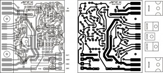
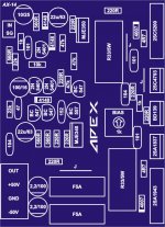
Still no luck with my NX14. Looks like I have to assemble the second channel. Anyway I see there is a difference between the two boards(NX14 V1 and NX14V2). I see two 100R resistors on the layout but not on the schematic. See attachment. The 22uF 63V cap on the schematic is replaced with a 2.2uF cap on board.....is this okey......
Macd
Hi Apex,
Still no luck with my NX14. Looks like I have to assemble the second channel.
Anyway I see there is a difference between the two boards(NX14 V1 and NX14V2). I see two 100R resistors on the layout but not on the schematic. See attachment. The 22uF 63V cap on the schematic is replaced with a 2.2uF cap on board.....is this okey......Macd
Attachments
Hi Apex,
Still no luck with my NX14. Looks like I have to assemble the second channel.
Macd
Two 100R resistor in series I use instead one 220R, 2,2uF is OK.
Do you measure voltages as I suggest?
Regards
Hello ALL!!!
Audio Amplifier-comentar !!??
Tank youuu!
'Nikko' coment sound of AX14 in local forum:
[es] - seme/pcb zastita pojacala i zvucnika
Regards
Hi Mile, do you have a diy amp suitable for a 38-0-38 volts transformer? I prefer for a bipolar output stage.
AX14 will work with +/-56V DC rail voltage.
Attachments
- Home
- Amplifiers
- Solid State
- 100W Ultimate Fidelity Amplifier