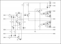
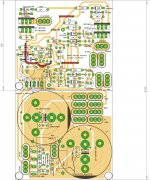
Pins 2 & 6 are the -IN pins.
Pin2 has R16 and R19 connected. These should be on very short traces to -IN.
Pin6 is unused.
Connect this channel to sit at half way between supplies.
I'm not sure about C3 & R7, maybe someone else can advise.
But C3 should maybe swapped with R7, so that the resistor is next to -IN.
Pin2 has R16 and R19 connected. These should be on very short traces to -IN.
Pin6 is unused.
Connect this channel to sit at half way between supplies.
I'm not sure about C3 & R7, maybe someone else can advise.
But C3 should maybe swapped with R7, so that the resistor is next to -IN.
Last edited:
it is my favorite hobby of all
If it is so,make a pcb for this amplifier protection")
yes thimios I was looking at the new schematic
I'm also working with another PCB with DC and 3 sec delay this one is not completed I still checking for errors I will see if I can find time to make this new protect Regards
Juan
http://www.diyaudio.com//www.pinterest.com/pin/create/extension/
Attachments
Very nice work!yes thimios I was looking at the new schematic
Regards
Juan
http://www.diyaudio.com//www.pinterest.com/pin/create/extension/
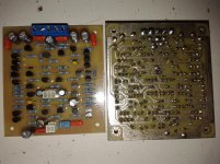
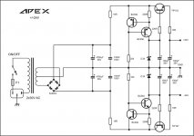
Do any of the transistors need a heatsink? Also, what is the ac voltage?
No need to use heatsink, AC is voltage from main transformer 2x30~50vac
OK, I reworked it and changed the IC to TL071. Hopefully this one is better.
Nice work, you can short SGND and GND
it is my favorite hobby of all
If it is so,make a pcb for this amplifier protection
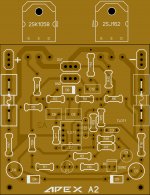
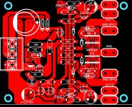
Here is a quick idea for layout of the protection PCB. It can be improved further based on suggestion of Mr. Mile or someone else
. Meanwhile I will keep on making it pretty.reg
prasi.
Attachments
Here is a quick idea for layout of the protection PCB. It can be improved further based on suggestion of Mr. Mile or someone else
reg
prasi.
is already pretty brother
Regards
Juan
http://www.diyaudio.com//www.pinterest.com/pin/create/extension/
Is your input GND connected to star GND?Hi
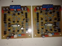
I completed building the AX-14 amplifier and i am getting 4vdc output on AX14 what could be wrong with it
My voltage is +/-20vdc.
please tell what is wrong
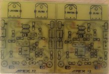
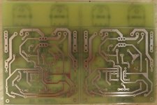
Very good looking symmetrical pcb!Any thoughts?
Yes, it's stereo.
Schematic from mister Mile http://www.diyaudio.com/forums/soli...imate-fidelity-amplifier-550.html#post4518802
Sprint layout file for own customizations attached
Oh, i see now i skipped 100K resistor from 5551 colector to +, sorry about that
Schematic from mister Mile http://www.diyaudio.com/forums/soli...imate-fidelity-amplifier-550.html#post4518802
Sprint layout file for own customizations attached
Oh, i see now i skipped 100K resistor from 5551 colector to +, sorry about that
Attachments
Last edited:
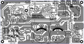
Need seggudtion psu...
You can use this simple PSU
Attachments
Yes, it's stereo.
Schematic from mister Mile http://www.diyaudio.com/forums/soli...imate-fidelity-amplifier-550.html#post4518802
Sprint layout file for own customizations attached
Oh, i see now i skipped 100K resistor from 5551 colector to +, sorry about that
Nice work, thank you
- Home
- Amplifiers
- Solid State
- 100W Ultimate Fidelity Amplifier