Sorry about all this. I am just trying to get the circuit working. After scouring the boards and measuring every component I decided to try building a spice file to give me a basis to work from. I made some mistakes in the file at first that caused me some problems. Now I have the file working but the circuit doesn't seem to work. I don't want to make any more changes to the boards until the circuit is at least proved in ltspice. Home etched boards don't take too many changes without damaged traces.
R27 should be 1meg, not 1milli. Also remove 8 ohm load resistor, since this is a preamp and everything will work properly in LTspice simulation.
Thanks. I forgot about the 1m in spice. I usually just enter 1000k. I changed it to 1meg and it runs perfectly. Better THD than your file. Your file is missing the 22R resistors on the rails. At any rate, now that I know it runs I can hopefully use it to troubleshoot my boards.
Thanks, Terry
Thanks, Terry
Thanks. I forgot about the 1m in spice. I usually just enter 1000k. I changed it to 1meg and it runs perfectly. Better THD than your file. Your file is missing the 22R resistors on the rails. At any rate, now that I know it runs I can hopefully use it to troubleshoot my boards.
Thanks, Terry
Can you post your voltage measurements?
Regards
Thanks. I forgot about the 1m in spice. I usually just enter 1000k. I changed it to 1meg and it runs perfectly. Better THD than your file. Your file is missing the 22R resistors on the rails. At any rate, now that I know it runs I can hopefully use it to troubleshoot my boards.
Thanks, Terry
When you are done post some square wave shots from your oscilloscope if its easy.
there was also another pcb layout version a few posts earlier made by another member. not tested though.
Attachments
Can you post your voltage measurements?
Regards
Attached
Attachments
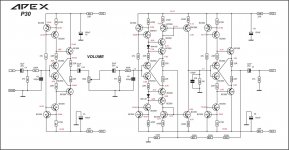
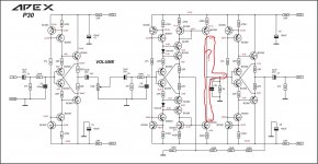
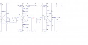
the ltspice that was first posted has q15,16,19,20 wrong against what is posted above
i fixed that and now get
Total Harmonic Distortion for vout : 0.726067%(0.726074%)
the input buffer Total Harmonic Distortion: 0.000017%(0.000000%)
i will post my dc voltages
something up with the gain stage to get that thd
edit: i am wondering if d1,2 need to be zeners for more voltage for q16,19
i fixed that and now get
Total Harmonic Distortion for vout : 0.726067%(0.726074%)
the input buffer Total Harmonic Distortion: 0.000017%(0.000000%)
i will post my dc voltages
something up with the gain stage to get that thd
edit: i am wondering if d1,2 need to be zeners for more voltage for q16,19
Attachments
Last edited:
the ltspice that was first posted has q15,16,19,20 wrong against what is posted above
i fixed that and now get
Total Harmonic Distortion for vout : 0.726067%(0.726074%)
the input buffer Total Harmonic Distortion: 0.000017%(0.000000%)
i will post my dc voltages
something up with the gain stage to get that thd
edit: i am wondering if d1,2 need to be zeners for more voltage for q16,19
There is mistake.
Attachments
Impossible.
Hi Mile,
Sorry I didn't notice that before posting. I think the reason is because that voltage is not steady and as I moved around the board it changed. I noted each voltage reading on each device as I read them. I should have looked and noticed that they were connected but I didn't and just noted the reading I had written down. At any rate, that is the least of the problems. As you can see by the rail voltages past the dropper resistors that something is pulling a lot of current. I have been over and over the boards and all of the devices are correct and oriented per the soldermask. Any ideas? Obviously the circuit works because the spice file works very well.
Thanks, Terry
Did both channels have same measurements?Hi Mile,
Sorry I didn't notice that before posting. I think the reason is because that voltage is not steady and as I moved around the board it changed. I noted each voltage reading on each device as I read them. I should have looked and noticed that they were connected but I didn't and just noted the reading I had written down. At any rate, that is the least of the problems. As you can see by the rail voltages past the dropper resistors that something is pulling a lot of current. I have been over and over the boards and all of the devices are correct and oriented per the soldermask. Any ideas? Obviously the circuit works because the spice file works very well.
Thanks, Terry
no one and no software interprets 1m as 1000000 (1M, 10^6)............I forgot about the 1m in spice. .............
m is universally used for 10^-3 = milli = 1/1000
All multipliers from k (10^3) downwards are lower case letters.
All multipliers ABOVE 10^3 are capital letters.
LTspice does not recognise 1M as 10^6, it needs 1meg.
hi guys,
terry,
when i was playing around last night with the sims, i separated the three functional blocks,input buffer,gain,output buffer, so i could isolate the stage having the problems.
input/output buffers are identical i discovered..
as it turned out i introduced a schematic error in the process which Mile found for me.
i ran a dc op point sim to put all the dc bias voltages in the sim which i posted with the updated spice directives.
good luck
LTspice does not recognize 1M as 10^6, it needs 1meg.
or 1e6 or 1000000
Last edited:
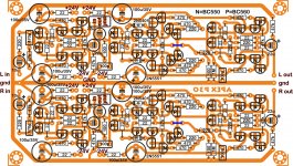
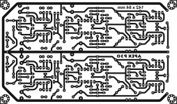
What about some pictures, Terry?
Here you go.
Attachments
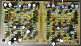
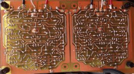
What about some pictures, Terry?
Here you go.
- Home
- Amplifiers
- Solid State
- 100W Ultimate Fidelity Amplifier