Spamming again.
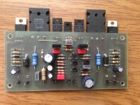
I did put ''yamaha'' style vas in to the ax11 amp. (thx Mile for guiding me).
What I like, the harsh top octave dissapeared. Now it is time for listening.
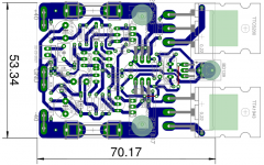
Bad news is the board is not mini anymore --> it is 6mm longer. For now it is a bit overcompensated and SR is approx 15V/us (it is enough anyway).
I did put ''yamaha'' style vas in to the ax11 amp. (thx Mile for guiding me).
What I like, the harsh top octave dissapeared. Now it is time for listening.
Bad news is the board is not mini anymore --> it is 6mm longer. For now it is a bit overcompensated and SR is approx 15V/us (it is enough anyway).
Attachments
 waiting the test result of this amp.
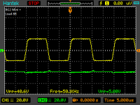
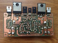
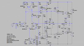
The board and the schematic bellow. I will have to try different compensations cause spice symulations is giving bit different results.
Nice work,
Regards
Option for 100W Ultimate Fidelity Amplifier.
A certain similarity with APEX AX11.
Obtained as upgrade of the power amplifier Pioneer A-30-S.
Excluded correction capacitors C327, C329 C331, C333
C311/ C312 put 2.2 pf (2.2 pf -12 pf) to pick up
- C313/ C314 put 47 pF. (33 pf -100 pf) to pick up
Result - very beautiful and natural sound .
PCB you may see in service manual link
PIONEER A-30-K A-30-S A-20-K A-20-S A-20 A-10-K A-10-S RRV4297 INTEGRATED AMPLIFIER Service Manual free download, schematics, eeprom, repair info for electronics
Very similar power amplifier with similar correction and PCB you may see in the service manual HARMAN KARDON AVR230 (5.1 channel) or HARMAN KARDON AVR335 (7.1-channel)
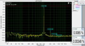
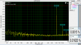
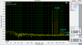
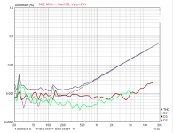
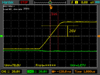
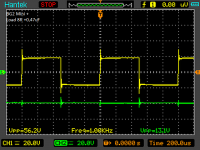
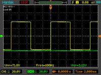
I have reduced 100p caps by the drivers to 33p (all compensation caps are 33p, the one in nfb network is not soldered). I think it is safe enough to build it. Bellow some scope readings.
Peter
Wow, that pioneer really looks similar, it only confirms that topology has something that it is ''sounding'' pleasent. I do not know why but I like it too.
The compensation at the LTP - in spice symulation was needed to keep the amp stable but in the real amp I think is not required, in my case it was 220R----2.2nF.
Regards
Attachments
Last edited:
The board and the schematic bellow. I will have to try different compensations cause spice symulations is giving bit different results.
You're doing some nice work.
You have mentioned simulations on the AX11. Have you posted a sim file somewhere?
Hi everyone,
Here is my realization on APEX HX11amplifier. see attachments
The PCBs are from this post http://www.diyaudio.com/forums/soli...imate-fidelity-amplifier-229.html#post3516547
But I have a problem with it. I cannot start normal this circuit. My power supply is +/-30V and +/- 45V. I check this pcb for mistakes but i cannot find it. I have +45V in the output.
Could you please give some idea where is the problem for resolve this issue?
Thanks a lot
BR,
Lyubo
Attachments
Here is my realization on APEX HX11amplifier. see attachments
The PCBs are from this post http://www.diyaudio.com/forums/soli...imate-fidelity-amplifier-229.html#post3516547
This reminds me of those I was doing back in the 70s. This is so cool!
Electronics hobbyism is a blast.
But I have a problem with it. I cannot start normal this circuit. My power supply is +/-30V and +/- 45V. I check this pcb for mistakes but i cannot find it. I have +45V in the output.
Could you please give some idea where is the problem for resolve this issue?
Well, I hope you didn't connect it to a real speaker that way!!!

Are you using any methods of soft start to bring it up and protect it? (light bulb, variac...)
It's time to take a multimeter and poke around checking voltages. After a full checkup.
Hi everyone,
Here is my realization on APEX HX11amplifier. see attachments
The PCBs are from this post http://www.diyaudio.com/forums/soli...imate-fidelity-amplifier-229.html#post3516547
But I have a problem with it. I cannot start normal this circuit. My power supply is +/-30V and +/- 45V. I check this pcb for mistakes but i cannot find it. I have +45V in the output.
Could you please give some idea where is the problem for resolve this issue?
Thanks a lot
BR,
Lyubo
2N5551 pins are reverted on this pcb or use BC546
Thanks for the quick support,
All the little transistors (TO92) are 2N5551 (NPN) and 2M5401 (PNP)
Could you please give me the circuit of this pcb?
Then I will try to fix this problem.
Thanks
Just rotate 180deg all TO92 transistors on your pcb
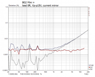
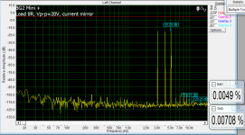
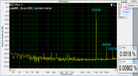
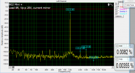
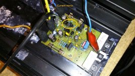
In my nature is that if someone is telling me DO NOT do it, this becomes first thing I am going to do. So I have soldered current mirror to the LTP, I just added 10pF in NFB for safety (all is stable with cap load), the top octave became more delicate and I am happy with it. The offset is 6mV and remains stable in fuction of temperature. Performance looks ok.
I do not know if that kind of front of the amp is technically ok but it survived 2h of playing the music anyway, I did not checked the output bias stability --> will do that tomorrow.
I do not know if that kind of front of the amp is technically ok but it survived 2h of playing the music anyway, I did not checked the output bias stability --> will do that tomorrow.
Attachments
- Home
- Amplifiers
- Solid State
- 100W Ultimate Fidelity Amplifier