Hi Madde,
the speaker you mention I believe is marked :
"500 watt max power" (tulisan saja)
& I don't think we need 500W amp to drive it, 200 to 300W is more realistic...
If you give it real 500W amp then I believe you will burn it out
(Full range in our town seems not so good, don't turn the bass knob so loud)
The speaker will be just fine with 300W amp if you not drive it until it clip
Usually AndrewT will give you some math, about rails, load & output power...
how many output transistor needed, etc...
So you can estimated how large the power supply, the heatsink, etc
let's waiting for Mr. AndrewT ...
he will explain to you better than me, better than most people I know here")
Thanks Bli John, yes it's true, in our town we doesn't have many choice about speaker brand and quality
i'm just thinking about power consumption of speaker and ability (better user more or less than true watt specification of speaker). if we give more, we can push to the limit ability of speaker, and if we give less than max watt, we only listen max of power used to drive the speaker. sorry for OOT
It is my point of view that speaker's power should be greater than amp's power.
My reasons are that,
1. It will give your amp a headroom for its power, the speaker will not saturate and not distort the sound.
2. If amp is driven at full power/volume, the speaker can handle it without worry of damage.
If amp's power is greater than the speaker's, the reverse of the above are true. Although you can still use a set up like this, but be mindful to set the volume of the amp to the speaker's ability to handle the power.
Thanks for your best answer Mr. Jaagut,
i get your point of your answer, and will be used for decide next project.
BR// Madde
mr. apex how can i increase the gain of ax20
Use preamp like this
Attachments
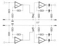
Ultimate Fidelity with MOSFETs
Hi Mile,
can i used K1058 and J162 in this schematic for final?
i have 2 pairs of them
i will create this in the separate project, after finished my big AX20 project
BR// Madde
Attachments
Hi Mile,
can i used K1058 and J162 in this schematic for final?
i have 2 pairs of them
i will create this in the separate project, after finished my big AX20 project
BR// Madde
I suggest F100 with HITACHI laterals from thread:
http://www.diyaudio.com/forums/solid-state/162081-dc-servo-mosfet-amplifier-15.html
Attachments
I suggest F100 with HITACHI laterals from thread:
http://www.diyaudio.com/forums/solid-state/162081-dc-servo-mosfet-amplifier-15.html
Thanks Sir,
this is i need
with 2 pairs final, and wow with DC servo (i hope, i understand what that means)i will read first that thread and will need lot of time
thanks again Sir Mile,
BR// Madde
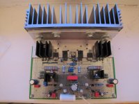
HIFI STEREO AX11
THANKS MR. MILE
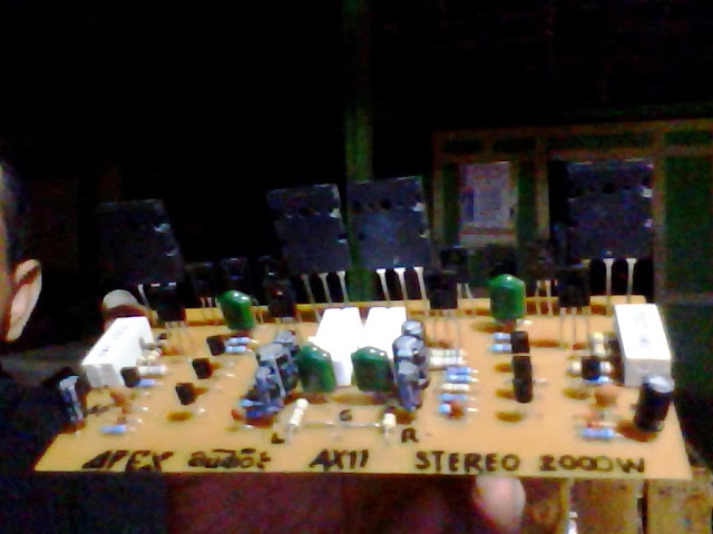

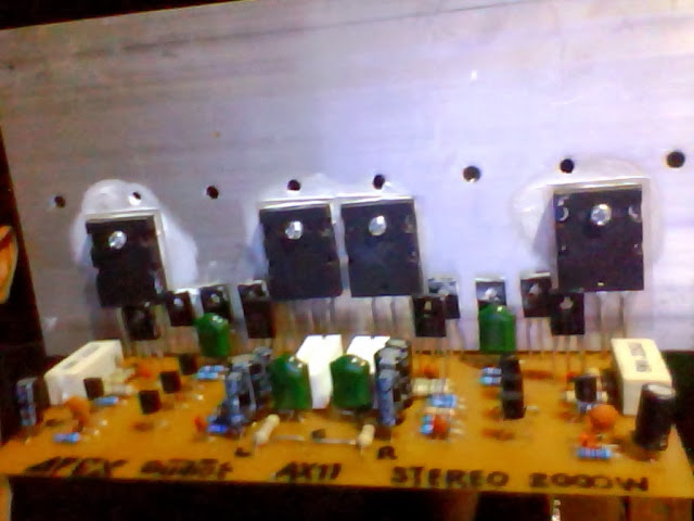

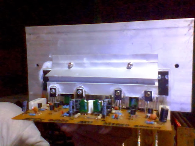

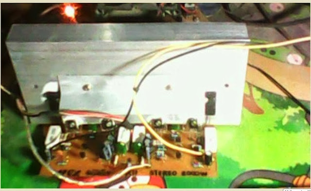
AX11 MY USE FOR 2 DAYS NONSTOP, SOUND VERY VERY GOOD WITHOUT INTERRUPTION.
THE NEXT STEREO AX11
CONCEPT CAR AMPLIFIER.PDF
THANKS MR. MILE
AX11 MY USE FOR 2 DAYS NONSTOP, SOUND VERY VERY GOOD WITHOUT INTERRUPTION.
THE NEXT STEREO AX11
CONCEPT CAR AMPLIFIER.PDF
THANKS MR. MILE
AX11 MY USE FOR 2 DAYS NONSTOP, SOUND VERY VERY GOOD WITHOUT INTERRUPTION.
THE NEXT STEREO AX11
Nice work,
Regards
Hello folks,
I just came across this thread along with CFA's amplifier thread. Someone please recommend the stable version of this schematic, It is so much information that is so difficult to find right away which one can try. Please point to a schematic or maybe few ? I'm eager to try this amplifier.
Thanks a bunch.
apexaudio
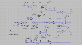
I know that you like ax11 amp. I like the bass ane middrage out of it but high octave is too ''sharp'' for me so I decided to draw a bit upgraded version i spice and it is rock stable and measures are good enugh to build it.
What would you think about it ?
thx
I know that you like ax11 amp. I like the bass ane middrage out of it but high octave is too ''sharp'' for me so I decided to draw a bit upgraded version i spice and it is rock stable and measures are good enugh to build it.
What would you think about it ?
thx
Attachments
apexaudio
I know that you like ax11 amp. I like the bass ane middrage out of it but high octave is too ''sharp'' for me so I decided to draw a bit upgraded version i spice and it is rock stable and measures are good enugh to build it.
What would you think about it ?
thx
Looks like AX14 with pure push-pull VAS from AX11... good idea
Regards
I think I will try It anyway. To 180deg reversing transistor can be easly cascoded for higher voltages anyway if needed.
I have made a drawing of ax14 but with cascoded j-fet front, the performance in the symulation is stunning but stability is not great in sim.
I will try to draw some layout for ax11+ amp.
I have made a drawing of ax14 but with cascoded j-fet front, the performance in the symulation is stunning but stability is not great in sim.
I will try to draw some layout for ax11+ amp.
I think I will try It anyway. To 180deg reversing transistor can be easly cascoded for higher voltages anyway if needed.
I have made a drawing of ax14 but with cascoded j-fet front, the performance in the symulation is stunning but stability is not great in sim.
I will try to draw some layout for ax11+ amp.
Hi boris ,go ahead!

Thimios.
Hello Wiljj78,
May you share the PCB Layout in Pdf for this Mini AX11.
you can PM me anj.dey@gmail.com
thanks & regards
AD
May you share the PCB Layout in Pdf for this Mini AX11.
you can PM me anj.dey@gmail.com
thanks & regards
AD
Nice Work
May you share the pcb Layout in Pdf for mini AX11 ,
you can PM me anj.dey@gmail.com
Rgds
AD
This is my AX-11 base on borys layout. PCB is very small
May you share the pcb Layout in Pdf for mini AX11 ,
you can PM me anj.dey@gmail.com
Rgds
AD
I think I will try It anyway. To 180deg reversing transistor can be easly cascoded for higher voltages anyway if needed.
I have made a drawing of ax14 but with cascoded j-fet front, the performance in the symulation is stunning but stability is not great in sim.
I will try to draw some layout for ax11+ amp.
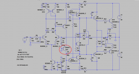
You can not use current mirror with pure push-pull VAS
apexaudio
I mean cacode like bellow if one 2n transistor wont eat whole supply voltage.
If someone need mini board for ax11 it is bellow. You can try to play with compensation caps at drivers from 33pf to 220pf to get sound you prefer.
I mean cacode like bellow if one 2n transistor wont eat whole supply voltage.
If someone need mini board for ax11 it is bellow. You can try to play with compensation caps at drivers from 33pf to 220pf to get sound you prefer.
Attachments
apexaudio
I mean cacode like bellow if one 2n transistor wont eat whole supply voltage.
If someone need mini board for ax11 it is bellow. You can try to play with compensation caps at drivers from 33pf to 220pf to get sound you prefer.
I mean you can't use current morror with Q14 and Q15, use only resistors and Q14 Q15 can be use as cascode for LTP
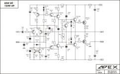
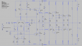
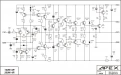
AX20 simulation
Here is a simulation done with ltspice for the AX20. As I'm trying to learn more on ltspice, I was curious about the AX20 and wanted to simulate it.
I embedded the models not in the ltspice default database so anyone using it should be able to run that sim with the same models.
I encountered a few discrepancies about part numbering around the output stages, so although most of the parts have the same number as on the schematic (attaching the one I used), some resistors have different numbers.
Once the simulation is able to run, I can immediately see that something can't work as it is on that schematic, as there is nothing to fix the potential on Q1's base, so I see a huge offset there at nearly 20V, so the output signal is totally offset as well and with a signal not pushing it to clipping, it does clip on the top side.
This thing is missing something to bring Q1's base to ground level...
Attachments
- Home
- Amplifiers
- Solid State
- 100W Ultimate Fidelity Amplifier