Nice work, this is class B hi-fi amplifier like QUAD 405 no need to change it to class AB there is many class AB amplifiers in this thread. BC546/556can be use with +/-56V maximum but if you want higer rail voltager use 2N5401/5551 and add two more pairs of output like in QUAD 606.
Regards
Thanks, the board needs improvements, it's just a first shot.
I am planning to get a bunch of those 2N5401/5551. I have other designs to build and those require such transistors.
I also have a bunch of 2N3055, 2N3773 and 2N3442 in stock (old), so that's why I'm interested in a quasi design for now. Just for the fun of it.
I think soldering smd parts is for those who still have a good eyesight and steady hands. I myself would never attempt to solder such parts (I'm too old for this now).
One thing that would be nice though is to try to get rid of the straps. And if using smd parts is just to stay within the original board size, then why not make the board a tiny bit wider, there is no physical limit to the board size, it turned out that way but there is nothing wrong with increasing its size a little.
If there are no smd parts to solder, I would consider building that little amp...
You have sample with no SMD parts above. SMD parts on board are all 1206 type so not so small at all. To avoid straps you need to swap to 2 layers and not only one.
Marc
Hot bulb resistance is R=U2/P, hot 100W/220V bulb have resistance 484 Ohms. If you want same resistance with 120V bulb must be 30W (P=U2/R),
Regards
Big Thanks.
hot bulb resistance indicates that there is probably a wiring fault.Hot bulb resistance is R=U2/P, hot 100W/220V bulb have resistance 484 Ohms. If you want same resistance with 120V bulb must be 30W (P=U2/R),
Regards
It's the cold or warm resistance that matters for a bulb that briefly flashes to a dull glow and returns to black.
Last edited:
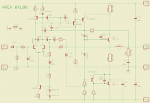
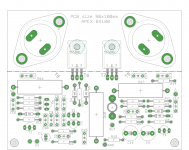
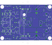
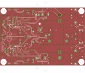
I added a resistor to lift the signal ground and changed the bc546/556 and bc640 to the 2n5401/5551.
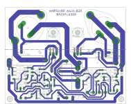
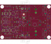
I had to rework the layout, rearranging many parts, mostly because the 2N have an opposite pinout compared to the BC. And adding that ground lifting resistor as well.
With all those transistors having a much higher Vceo, the rails can go much higher. This could be a good use for the bunch of 2N3773 that I have in the old stock.
I think the C11 issue needs to be verified. Is it oriented right? This is the way I thought it would need to be.
I avoided using straps, so this is a nice thing.
The grounding scheme could use some improvements, would anyone have input on this point?
Attachments

I was wondering. Why are there so many caps around the input stage? The C3,C4,C7,C8,C9 and C10, although all of rather small value, are they really all that necessary? Was the amp so unstable without all of them? Wouldn't they hamper the slew rate and bandwidth somewhat?
And I was also wondering about the crossover distortion, due to the class B only mode, there must be some.
And I was also wondering about the crossover distortion, due to the class B only mode, there must be some.
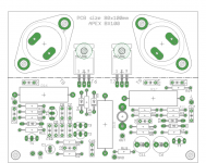
I made the board myself to test my layout.
I would really like a few boards of that AX11-MK2 with the TO-3s on it. Was that layout made by you?
I have a bunch of MJ15003/4, MJE340/350 and MJE15030/31, and even the BD139/140, plus I will have 2N5401/5551 and MPSA42/92 very soon. So I will have most of the needed parts and I'd like to build this.
Have any boards been made beyond a single prototype? No group buy?
I priced out a board of similar size lately, with a european board maker that's been the cheapest that I found, and the unit price could drop well below 10euros only by making 10 boards. I think a reasonable group buy on this could be put together and get several dozen boards, bringing the cost down much further.
Would that be of interest to anyone? I would want several boards myself.
yes, but that hot condition only applies when there is a wiring fault or if the builder misunderstand the purpose and tries to bias their amp with the bulb tester still in line.Bulb is PTC resistor with low resistance with low current, but if current thru bulb increase resistance will increase transformer voltage will drop and protect amplifier.
When the transformer and/or rectifier and/or smoothing capacitors and/or the unbiased amplifier are wired correctly the current draw is so low that the filament in the bulb tester does not "light up" it remains cold or warm, not hot.
Hot resistance does not apply to correctly wired equipment.
yes, but that hot condition only applies when there is a wiring fault or if the builder misunderstand the purpose and tries to bias their amp with the bulb tester still in line.
When the transformer and/or rectifier and/or smoothing capacitors and/or the unbiased amplifier are wired correctly the current draw is so low that the filament in the bulb tester does not "light up" it remains cold or warm, not hot.
Hot resistance does not apply to correctly wired equipment.
It depending the bulb that is used & the load.
I use light bulb as a soft start circuit, it is glowing quite bright until I bypass the bulb to turn on the whole amp...
When the amp is not biased the bulb isn't bright,
but after the amp biased the bulb shine's so bright.
Andrew T,
can you estimated the value for the bulb(watt) that we shall use and for the load(VA)?
cause I just try with trial & error

BTW just yesterday the bulb tester save me again, cause false wiring the transformer
Regards
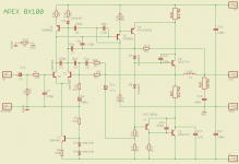
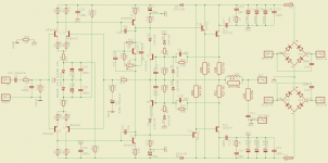
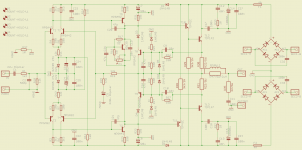
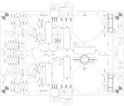
Here is a schematic I'd like to share.
This one is totally symetric from end to end, and each stage is kept at a low gain for a low open loop gain on the amp, then with a reasonable feedback. This is a low tim design.
I'm planning to put the power supply all on the board with it, so only the transformer's secondary windings are directly coming on the board, limiting the external wiring.
Then perhaps an XLR plug could be added right on the board as well for input, eliminating even more wiring.
This can lead to adding a power on delay relay, perhaps with a mute as well, and a temperature sensor on the heatsink to cut off the output relay in case of overheating, and then an output SpeakOn plug also right on the board. This could end up as an all-in-one with hardly any wires.
Attachments
yes, but that hot condition only applies when there is a wiring fault or if the builder misunderstand the purpose and tries to bias their amp with the bulb tester still in line.
When the transformer and/or rectifier and/or smoothing capacitors and/or the unbiased amplifier are wired correctly the current draw is so low that the filament in the bulb tester does not "light up" it remains cold or warm, not hot.
Hot resistance does not apply to correctly wired equipment.
I don't use bulb for first test only 150 Ohms 20W resistor instead main fuse.
Bulb test passed
I fed both channels one after the other with 40w bulb in line - I don't have 30w in hand. Everything seems ok without any burnt smell and or spark. I took +/- 35.4v on both channels after fuse to 15004/3. On output there are -2.3mv and -6.5mv respectively, but I couldn't read any current across 0.22 ohm even I turn the 50k trimmer real hard. ( I have 3.3K parallel with a 50k trimmer so to make it around 3.2k. I'd like to drive them hotter after sometime ). What I should do now ??
Regards
Albert
Double check there is no continuity from the case of the to-3 and the chassis. I had a devil of a time when screwing them to the L bracket.
I had to sand the surfaces around the drill holes a lot to keep the outputs isolated.
I am using silpads.
Double check there is no continuity from the case of the to-3 and the chassis. I had a devil of a time when screwing them to the L bracket.
I had to sand the surfaces around the drill holes a lot to keep the outputs isolated.
I am using silpads.
I will double check that. What I did was fitting a heat shrink tube to the screws, n that had been checked for couple times before I turn the power on, but no harm to check one more time.
Be careful the bias will come on fast after quite a few turns so go slowly on the pots.
Thanks for the head up. I thought I better have them tuned back to around 3.2k before I turn the amp on again.
- Home
- Amplifiers
- Solid State
- 100W Ultimate Fidelity Amplifier