At "nuclear" volumes the TMC kicks in. Also, the sound stays the same even with gross misbiasing (TMC "eats" crossover distortion).
Overall , this is the "perfect amp" , but with TMC .. it stays perfect over a greater range.
My problem with this amp is that it is so distortion-less , the only thing left was the junction noise of the input pair... at ANY volume. So , the cascode/MPSA18's are the next step , plus big FAT audiophile input caps (C1 - Below).
(Below 2) shows the correction signal which is fed back to the miller loop , it correlates to the crossover point. The remaining high order distortion (produced by the outputs) is also gone in an FFT.
OS
Overall , this is the "perfect amp" , but with TMC .. it stays perfect over a greater range.
My problem with this amp is that it is so distortion-less , the only thing left was the junction noise of the input pair... at ANY volume. So , the cascode/MPSA18's are the next step , plus big FAT audiophile input caps
(C1 - Below).(Below 2) shows the correction signal which is fed back to the miller loop , it correlates to the crossover point. The remaining high order distortion (produced by the outputs) is also gone in an FFT.
OS
Attachments
Last edited:
hello.i built dx blame st 1.5.my problem is when start up without play song it become very hot.if play the song more heat produce.i follow and use all recommended component in this thread.why this happen and solution to me?
Have you adjusted bias correctly? Removing rail fuses, maintaining series 100 ohm resistors, you should read something around 4.7VDC through their leads. Start with a high value for the trimmer (> 300 ohms), then lower it while adjusting.
The Blame amps I have built run very cool. Any cooler and you'd think I lived in Antartica. Less than luke warm to touch after playing for an hour at loud levels. You will need to provide more info to the smart guys here (I am excluded) for them to make a feasable comment. Some pictures would help. Have you a camera with a macro mode?
Regards
Niss_man
Regards
Niss_man
hello.i built dx blame st 1.5.my problem is when start up without play song it become very hot.if play the song more heat produce.i follow and use all recommended component in this thread.why this happen and solution to me?
you are right.when i remove the fuse , heatsink is cool while playing song.but when i increase volume sound bass more broken.this fuse using or not?or remove while setting bias?when multimeter parellal with resistor at fuse i get more than 6 volt.how to set bias?Have you adjusted bias correctly? Removing rail fuses, maintaining series 100 ohm resistors, you should read something around 4.7VDC through their leads. Start with a high value for the trimmer (> 300 ohms), then lower it while adjusting.
you are right.when i remove the fuse , heatsink is cool while playing song.but when i increase volume sound bass more broken.this fuse using or not?or remove while setting bias?when multimeter parellal with resistor at fuse i get more than 6 volt.how to set bias?
You shouldn't play music with the fuses removed! What smartx21 means is have no music playing. No inputs. Just measure across the 100ohm resistor (across fuse terminals). The basic setting is 4.7v. This means a standby current of 47mA. Still if you have 6v accross the fuse (without input) 60mA is still acceptable. You probably have issues elsewhere. Photos?
Regards
Niss_man
thanks smartx21.i get the solution.my trimmer install problem.now i can setting bias.sound good.bass smooth.i like it.heatsink cool.but why must 4.7 volt?this value depend on power supply voltage or speaker load or this standard value could i just follow?You shouldn't play music with the fuses removed! What smartx21 means is have no music playing. No inputs. Just measure across the 100ohm resistor (across fuse terminals). The basic setting is 4.7v. This means a standby current of 47mA. Still if you have 6v accross the fuse (without input) 60mA is still acceptable. You probably have issues elsewhere. Photos?
Regards
Niss_man
this amp powerfull.can i add sc5200 to get more power?and what must i change for standart dx blame st pcb?
The value of 4.7VDC is a project guideline. Removal of fuses only for adjustments. Here you can find specs for a more powerful DX Blame ST, the MKII Supercharged: www.dx.kinghost.net. Besides doubling OPs, rail voltages are raised, and some parts values do alter. Be careful and enjoy!
Blame ST + TMC
TMC elements I used are: )look at schematic OS presented in #1119)
C13=150p, C12=470p and R19=220R
Simulated distortion is: (I do not have equipmnt to measure it on real amp)
Circuit: * C:\dado\Audio\DadoAmp\DX-blme-st-TMC.asc
Direct Newton iteration for .op point succeeded.
Heightened Def Con from 8.13802e-012 to 1.00814e-009
Fourier components of V(vin)
DC component:1.35985e-005
Harmonic Frequency Fourier Normalized Phase Normalized
Number [Hz] Component Component [degree] Phase [deg]
1 3.000e+03 5.060e-01 1.000e+00 -0.01° 0.00°
2 6.000e+03 1.890e-08 3.735e-08 -109.21° -109.20°
3 9.000e+03 1.048e-09 2.071e-09 128.10° 128.11°
4 1.200e+04 9.838e-10 1.944e-09 -166.59° -166.59°
5 1.500e+04 1.255e-09 2.481e-09 12.46° 12.46°
6 1.800e+04 2.420e-09 4.783e-09 -6.04° -6.04°
7 2.100e+04 3.585e-09 7.085e-09 8.81° 8.82°
8 2.400e+04 5.019e-09 9.919e-09 -2.20° -2.19°
9 2.700e+04 5.629e-09 1.113e-08 7.64° 7.65°
Total Harmonic Distortion: 0.000004%
Fourier components of V(vout)
DC component:-0.0176293
Harmonic Frequency Fourier Normalized Phase Normalized
Number [Hz] Component Component [degree] Phase [deg]
1 3.000e+03 1.378e+01 1.000e+00 -0.49° 0.00°
2 6.000e+03 4.255e-05 3.088e-06 -120.73° -120.24°
3 9.000e+03 8.061e-06 5.850e-07 162.67° 163.16°
4 1.200e+04 1.039e-05 7.538e-07 179.46° 179.95°
5 1.500e+04 7.615e-06 5.526e-07 171.69° 172.18°
6 1.800e+04 6.895e-06 5.004e-07 -178.84° -178.35°
7 2.100e+04 6.583e-06 4.777e-07 166.70° 167.19°
8 2.400e+04 5.110e-06 3.709e-07 -177.22° -176.73°
9 2.700e+04 6.143e-06 4.458e-07 164.07° 164.56°
Total Harmonic Distortion: 0.000340%
It could be lowered even more but I have gone for better stability!!!!
Simulated distorton for Blame ST with Miller compensation:
Circuit: * C:\dado\Audio\DadoAmp\DX-blme-st.asc
Direct Newton iteration for .op point succeeded.
Heightened Def Con from 8.13802e-012 to 1.00814e-009
Fourier components of V(vin)
DC component:1.36071e-005
Harmonic Frequency Fourier Normalized Phase Normalized
Number [Hz] Component Component [degree] Phase [deg]
1 3.000e+03 5.060e-01 1.000e+00 -0.00° 0.00°
2 6.000e+03 1.693e-08 3.346e-08 -149.21° -149.20°
3 9.000e+03 1.177e-08 2.327e-08 85.96° 85.96°
4 1.200e+04 7.397e-09 1.462e-08 177.52° 177.53°
5 1.500e+04 2.137e-08 4.223e-08 78.32° 78.32°
6 1.800e+04 2.674e-09 5.285e-09 173.90° 173.90°
7 2.100e+04 2.887e-08 5.705e-08 73.61° 73.61°
8 2.400e+04 1.441e-09 2.847e-09 10.52° 10.53°
9 2.700e+04 2.964e-08 5.858e-08 68.23° 68.23°
Total Harmonic Distortion: 0.000010%
Fourier components of V(vout)
DC component:-0.0176098
Harmonic Frequency Fourier Normalized Phase Normalized
Number [Hz] Component Component [degree] Phase [deg]
1 3.000e+03 1.378e+01 1.000e+00 -0.22° 0.00°
2 6.000e+03 4.406e-05 3.197e-06 -159.06° -158.85°
3 9.000e+03 2.767e-05 2.008e-06 100.50° 100.71°
4 1.200e+04 2.606e-05 1.891e-06 177.24° 177.46°
5 1.500e+04 4.822e-05 3.499e-06 91.98° 92.19°
6 1.800e+04 1.992e-05 1.446e-06 176.89° 177.11°
7 2.100e+04 6.358e-05 4.614e-06 87.83° 88.05°
8 2.400e+04 1.526e-05 1.107e-06 176.62° 176.84°
9 2.700e+04 6.315e-05 4.583e-06 86.13° 86.34°
Total Harmonic Distortion: 0.000870%
dado
Figures are nice but has anyone heard the Blame ST with TMC mod with their own ears, or only on simulated on spice? If anyone has actually heard the difference using their ears could they please say if there is any audible difference between the 2 ?
Dadod. Have you heard of a place called Oroslavje?
Regards
Niss_man
Dadod. Have you heard of a place called Oroslavje?
Regards
Niss_man
Last edited:
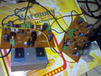
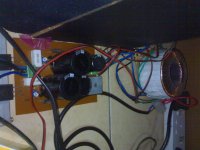
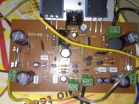
this my picture.stereo dx blame st amp and voltage regulator by apex design.You shouldn't play music with the fuses removed! What smartx21 means is have no music playing. No inputs. Just measure across the 100ohm resistor (across fuse terminals). The basic setting is 4.7v. This means a standby current of 47mA. Still if you have 6v accross the fuse (without input) 60mA is still acceptable. You probably have issues elsewhere. Photos?
Regards
Niss_man
i interested with this amp.can anybody give way to add 3 pair or 4 pair of 2sc5200 to get more power output.
Attachments
what different between this circuit with from ?Soon we gonna have all stuff at Greg Erskine home pages too.
Greg's Web Site
down this page, attached the schematic and layout...much more to come!
regards,
Carlos
what different between this circuit with from * ?
I think you should read and follow this thread:
http://www.diyaudio.com/forums/soli...tions-dx-blame-mkii-supercharged-release.html
Regards,
Max.
Hi Carlos,
I finished Blame-ST but with the touch. After reading about TMC by Edmond Stuart I could not but try it. "http://www.diyaudio.com/forums/solid-state/94676-bob-cordell-interview-negative-feedback-304.html"
Good start was Blame ST and here it is, Blame-ST-TMC.
Voltage is +-40V a bit more and the feedback resistance a 22k/820 same ratio but higher input resistance. PCB hand made.
The loudspeakers are hand made Seas woofer and mid/high ribon by Newform Research.
I like the sound of the combination very much.
Here is schematic and LTSpice simulation.
hi dadod, can you share your pcb design
this my picture.stereo dx blame st amp and voltage regulator by apex design.
i interested with this amp.can anybody give way to add 3 pair or 4 pair of 2sc5200 to get more power output.
q8 must be in fixed in the main heatsink
Uncle Charlie is moving along nicely ....
Figures are nice but has anyone heard the Blame ST with TMC mod with their own ears, or only on simulated on spice? If anyone has actually heard the difference using their ears could they please say if there is any audible difference between the 2 ?
Dadod. Have you heard of a place called Oroslavje?
Regards
Niss_man
I believe OS had commented on it , it was later edited ....he did believe the TMC mod made the amp better ...
Uncle Charlie is moving along nicely ....
I believe OS had commented on it , it was later edited ....he did believe the TMC mod made the amp better ...
It absolutely is worth the addition of 4 pads (2 components) which can be omitted/ jumpered for traditional compensation. I do it like (below) , the PCB reflects this as well.
OS
Attachments
He is really away for a while, and I am not his representative. I only try to help, since I built this amp twice and know these obvious things.Uncle Charlie is moving along nicely ....
Regards,
Max.
- Status
- This old topic is closed. If you want to reopen this topic, contact a moderator using the "Report Post" button.
- Home
- Amplifiers
- Solid State
- Dx Blame ST - Builder's thread - post pictures, reviews and comments here please.