hello,
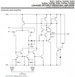
can somebody say to me what's wrong in this Tina 7 T.I. simulation file ? I have replicated the TL071 schematic given in the datasheet. It delivers good figures regarding power supply drain, gain-bandwith product and slew-rates for all non-inverting gain configurations between 10 and 1000. I have not yet tested the inverting gain configuration.
For smaller gains like x2 or x1 unity gain buffer, the results are highly variable, depending on details like :
- load resistance
- load capacitance
- serial resistance of the generator
- input capacitance
If you simulate with a 22K load resistor and 33pF load capacitor, 100 ohm serial resistance of the generator, and 10 pF input capacitance, you will get alarming simulation results.
Set the load to 100K, decease the input capacitance to 5pF, and you'll get a unity buffer gain plot showing a MHz oscillator.
What will thus happen if one puts a TL072 wired as unity gain buffer after a volume potentiometer ? This is a case where the serial resistance of the generator can go from a few ohms (zero volume or full volume, or channel short-circuit by the balance pot), to more than 50K (a 100K pot at mid position).
Don't you think there is an issue, here ? Where am I wrong ?
I'm attaching a few files.
The .zip contains the Tina 7 T.I. schematic ready for simulation.
Cheers,
Steph
Attachments
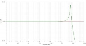
Definitely wrong answer. The simulated GBW is 3 MHz. See attached pictures, when the amp is configured for a x1000 gain.Your simulated schematic has too much bandwith, as the GBW of the TL071 is no more than 3 mhz.
Attachments
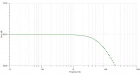
Definitely wrong answer. The simulated GBW is 3 MHz. See attached pictures, when the amp is configured for a x1000 gain.
Yes, for a 60db gain , i m wrong, but for a 0db gain , i m right and
you are wrong....
Before jumping to this conclusion, make a test using toshiba jfets...
hello wahab, I think we are half way the truth. Using a x1000 gain, the GBW of the simulated TL071 is very close to 3 MHz. Using a gain of x1 (unity gain buffer), the GBW of the simulated TL071 gets a little bit inflated, but not so much. Basically, I think the model behaves okay. I agree that the transistors used in the model surely need better parameters, to cope with IC technology. I don't think NPNs and PNPs in integrated circuits like the TL072 behave like NPNs and PNPs that are available as individual components. If you could be more specific in your answer, like suggesting some parameters tweak in the NPN and PNP models, that would help. Same for the PFETs : what model would you advise ?
I had trouble with discrete transistors when I modeled a JLH
headphone amp based upon TI 47LS04 logic gates. Currents
passed by the datasheet specified internal resistors proved
insufficient to bias even the smallest LTSpice discrete model.
I remember ended up paralleling the resistance values of the six
gates instead of scaling down the transistors. So, I never really
solved the problem the correct way. But I seen the same what
you are fighting with for sure...
It's not clear to me what is the purpose of this simulation, but if you want to reproduce the behavior of TL071, then you have to pick an input JFET with lower gm, e.g. ~0.3 mS at 0.12 mA. J175 is not too far but still a little a bit too high, I think. Using 2SJ74 goes to the opposite direction from J175 (higher gm). Also, the Ft of PNP transistors in TL071 is merely a fraction of discrete PNPs (~5MHz). Maybe inserting resistors in base of output emitter follower Tr, or inserting a cap to connect the two bases can tame the oscillation?
Regards,
Satoru
Regards,
Satoru
Hello, thank you for the valuable info you provided. Actually, I'm trying to see what kind of compromizes are done inside audio opamps for getting them (more or less) stable if used as unity gain buffers, with uncertain source impedances and with uncertain load impedances.It's not clear to me what is the purpose of this simulation
On one hand, I have the impression that internally compensated audio opamps like TL071 are building blocks for dummies, vastly over-compensated for allowing dummies using and abusing them, and never getting unstability.
On the other hand, I don't understand how faster audio opamps like OPA134 are stable in a huge domain. What kind of tricks do they use, for getting their behaviour nearly independent of loading, and nearly independent of source impedance ? If I'm designing such fast opamp using discretes, I can't get a stable unity gain follower. What do they put inside for getting speed, slew-rate, and stability, all at the same time ?
Those last weeks I'm concentrating in modelling power amplifiers, using an audio opamp as front-end. Using an audio opamp as front-end seems an interesting path for DIYers :
- they can select the audio opamp of their choice (if detailed instructions provided about stability for each supported model)
- they don't need to buy unobtainable dual matched JFETs
- they don't need to buy quantities of single JFETs, and match them
- they don't need to wire the associated current source, cascodes, and so
There are some interesting features, using an opamp as front-end :
- using a quality JFET audio opamp at the input, one may supppress the input capacitor, and one may apply DC amplification
- one can apply a conventional topology, using the opamp output, and boosting it a little bit by an intermediate gain stage using discretes
- one can apply a "current feedback" mode amp, using the current that is taken by the opamp supplies, and feeding the driver with dynamic currents that are more than twice the driver quiescent current
- one can apply weird topologies like improved BUZamp, revisited QUAD405, or nanoQSC, at minimal cost and minimal complexity
Last time I have used a pre-programmed model (TL072), I went fooled by the power supplies of the pre-programmed model not following the current that's delivered at the output. This ruins simulation for "current mode" topologies, where it is the supply taken by the audio opamp that's activating the driver.
Regards,
Steph
Last edited:
hello dear friends,
here you can see that the built-in Tina 7 T.I. TL071 model is wrong.
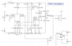
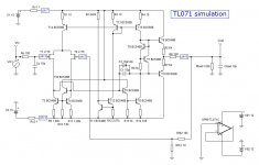
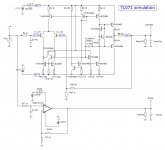
Please have a look to the schematic. You can see both circuits being wired as x10 amplifiers, loaded by 330 ohm, with a 1V 1kHz sinus at the input. That's 10V on the output, hence about 30mA current into the 330 ohm load. This current is supposed to come from the power supplies.
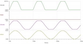
Please have a look to the system waveforms. The built-in Tina 7 T.I. TL071 model is wrong regarding the current taken by the power supply pins.
The hand-made model using discrete is better. It shows the current being taken by the supply pin, and it shows the limited current that's available at the output of the TL071 (clipping).
For some audio applications, like current feedback topologies using a TL071 as front-end, the supplies are the signal.
Hope this explaination clarifies why this hand-made TL071 simulation has been undertaken.
Cheers,
Steph
here you can see that the built-in Tina 7 T.I. TL071 model is wrong.
Please have a look to the schematic. You can see both circuits being wired as x10 amplifiers, loaded by 330 ohm, with a 1V 1kHz sinus at the input. That's 10V on the output, hence about 30mA current into the 330 ohm load. This current is supposed to come from the power supplies.
Please have a look to the system waveforms. The built-in Tina 7 T.I. TL071 model is wrong regarding the current taken by the power supply pins.
The hand-made model using discrete is better. It shows the current being taken by the supply pin, and it shows the limited current that's available at the output of the TL071 (clipping).
For some audio applications, like current feedback topologies using a TL071 as front-end, the supplies are the signal.
Hope this explaination clarifies why this hand-made TL071 simulation has been undertaken.
Cheers,
Steph
Attachments
For some audio applications, like current feedback topologies using a TL071 as front-end, the supplies are the signal.
Would you use a TL071 as front end in a design of yours ?...
Hi Steph,
For JFET-input amplifiers, there is a mutual relationship between the GBW, slew-rate and stability. The gm of JFET affects the compensation cap size, which sets the GBW, while the JFET current (together with compensation cap) sets the slew-rate. If the GBW is too high, the amp would be unstable easily. If the GBW is kept low enough (~3MHz for power amp? How do you think, folks?), the compensation capacitor has to be larger, so the slow slew-rate. Picking up a low gm JFET leads to a higher slew rate stable amp.
Best regards,
Satoru
Would you use a TL071 as front end in a design of yours ?...
Hi Wahab,
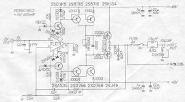
Steph is talking about a topology like following amp, designed by Toru Kuroda in 1982, (taken from a web site http://home.b04.itscom.net/helium/audio/poweramp/index.html). Please note an unusual way of using TL071.
Best regards,
Satoru
Attachments
Hi Wahab,
Steph is talking about a topology like following amp, designed by Toru Kuroda in 1982, (taken from a web site http://home.b04.itscom.net/helium/audio/poweramp/index.html). Please note an unusual way of using TL071.
Best regards,
Satoru
It s not unusual at all..
Have you already messed around such a circuit?...
It s not unusual at all..
Have you already messed around such a circuit?...
Hello Wahab,
I don't have any other schematics in which an opamp is used like this. Do you have more examples to add to my schematics collection? No, I haven't build this amp.
Regards,
Satoru
Kuroda's topology is first described in 1969 by the late great Bob Widlar in National's application note no 29 page 16
http://www.national.com/an/AN/AN-29.pdf
Some level shifting is needed to use higher voltage supplies of course.
http://www.national.com/an/AN/AN-29.pdf
Some level shifting is needed to use higher voltage supplies of course.
Hello, thank you for the valuable info you provided. Actually, I'm trying to see what kind of compromizes are done inside audio opamps for getting them (more or less) stable if used as unity gain buffers, with uncertain source impedances and with uncertain load impedances.[snip]Steph
Hello Steph,
Interesting exercise for sure. But please remember that what you see in the datasheet circuit for the TL071 is just the top of the iceberg. There is much more in that opamp that you don't see, many more transistors, diodes and parasitic capacitances. These are not on the datasheet and will make it very difficult to simulate it realistically.
An other possiblilty is to use the spice model listing for it as a discrete circuit and play with that. You could get a little bit closer to the real opamp, but still not completely.
jd
Can you advise a proper spice model listing for the TL071, preferably compatible with Tina 7 T.I. and/or with LTspice IV ? I would like to test-run it.Hello Steph, another possiblilty is to use the spice model listing for it as a discrete circuit and play with that. You could get a little bit closer to the real opamp, but still not completely.
The quickest solution to your problem would be to add this to the Standard TL071 model (presumably Boyle macro-model)
Power Rail Correction Current
This models the supply currents.
I used a similar technique when I wanted to model a Kuroda type amp but using a NE5534 + darlingtons to make a cheap good amp. The model worked but I never got around to trying it in practice.
Hi Satoru. Going OT here. Do you have the schematic of Kuroda's low distortion oscillator?
Spice model
TI has a macromodel for the TL072, see attached. Should be compatible to any Spice simulator.
I'm sure they also have a detailed component level model but I don't think they will release that.
But the macromodel is a start and you could see how it reacts and compare with a discrete implementation.
jd
Attachments
- Status
- This old topic is closed. If you want to reopen this topic, contact a moderator using the "Report Post" button.
- Home
- Amplifiers
- Solid State
- TL071 hand-made simulation using discretes