 Mains isolation is very important.
Admit tingly I'm not particularly a SMPS guy, but it doesn't look like that circuit is intended for mains use. That's a good way to end up covered up pushing daisies up from the dirt, if you get my drift.
Sorry, I've forgot to mention that

I'll post it in car section.
EDIT1: PLEASE DON'T DISCUSS ABOUT THIS SMPS IN THIS TOPIC. I've opened separated topic where we can discuss this one.
http://www.diyaudio.com/forums/car-audio/163419-boras-smps-design-schematic-pcb.html#post2123824
Last edited:
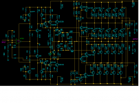
Seeing as you are inviting opinionsI've found this schematic and I think it is awesome design. It is very popular project in Balkan region. The design is by boro.
What do you think about it?
As has been mentioned, there is no way this amp would stick out 1KW 4ohm clean even with a fully regulated supply. I must admit i like the idea of all N channel mosfet amplifiers but they lose out on efficiency due to fair sized voltage drops on both positive & negative rails. This is due to the gate voltage of the power mosfets.
It's simple to cure the problem on the positive rail, simply use a higher rail voltage for the drivers. Try sussing out a way of doing it on the negative rail though
Taking the positive rail, this beast first of all drops 0.7V via the diode feeding the front end & Vas, then another 1.4V accross the Vas constant current. Another 0.7V accross the driver & at least 4 - 6V or more driving the mosfet gates (more nearer the positive rail) & then drops accross the source resistors.
It's a fair design, pity about the MJE340/50 though... I'm sure there must be better than transistors than those for Vas duty, why not use the MJE transistors that are used as drivers - they are miles faster.
Then how can I make 5000W amplifier?
I DON'T NEED IT I just want to make it so I can show it everywhere and I can boast around.
Hey not necessarily... just Optically isolate the audio ins, and use standard 240V UL approved home electric stove appliance socket for the speakers! throw in some fuses, and you're in business! (LOL). Hey, for the cost of the transformer, we've all thought about things like that!
Geesh.. +/- 170VDC! 3.6 Peak KW into 8 ohms! Now that's a PA system!
Giving discredit where it is not due......
The design is very good.
VAS could be a faster device, sure. Small potatoes.
Split drivers is a sensible and common practice in very high power amps. It does not create any matching issues; bipolar Vbe differences are much less than Vgs variations in the mosfets they are driving anyway.
Compensation looks to be very well sorted.
Should measure quite well and would definitely sound very good with a small excess of even harmonics over odd.
Agree it may not do 1000W. Let's just say it will easily do 700W. That's almost one horsepower, should be enough for all but heavy metal vampires?
Give the design some credit guys, instead of picking minor faults. High power amps are extremely difficult to stabilise for all loads, and Dr Bora has done a really good, textbook job here.
Congratulations, Dr Bora!
Hugh
For very high load regulation and reliability it might be considered to use 2 60Hz power transformers. One transformer can be wired directly to the line and selected to supply 70 or less % of the power and the second only needs the balance of output voltage capacity at full rated current. Drive the primary of the smaller transformer with a low speed isolated switching section that loads a bridge rectifier. Loop speed doesn't need to be very high when using an output filter bank designed for conventionaly unregulated rectifier supply. Similar circuits have been designed in the past with triacs but possibly a FET/bridge combo could have lower noise and higher efficiency by keeping funny waveforms out of the iron.
Last edited:
These high power amplifiers are not practical if they are not either Class G (tracking rails with switching regulators), class H (switched rails) or class D (plain switching).
See this thread:
http://www.diyaudio.com/forums/solid-state/162408-900w-h-class-pa-amp-limiter.html
This rail switching approach is simple and elegant.
See this thread:
http://www.diyaudio.com/forums/solid-state/162408-900w-h-class-pa-amp-limiter.html
This rail switching approach is simple and elegant.
Yes, I agree Eva. Nowdays, especially for PA, it seems class D is in vogue. Another trick being used is 2Ohm speakers (already pretty much standard in the latest mini-comp consumer products).
BTW, th e newer base guitar amps are all class D (with SMPS PSU's). The roadies must love them.
BTW, th e newer base guitar amps are all class D (with SMPS PSU's). The roadies must love them.
If anyone is even considering that amp (it would work with some effort and refinement) build this instead. It *does* work - I have three of them.
The new ones are class H, however (but not ready for release).
Note: The "BDX77" are diode-connected fully isolated transistors. Mount one to the NPN driver, one to the PNP driver, one to an NPN output (in the lower bank), and one to a PNP. This will allow the use of SEPARATE HEAT SINKS without thermal runaway.
Attachments
Last edited:
"You all people just talk about every design that it is not possible to deliver that amount of power "
I think we know how to figure out what is real, and what is fiction.
Do you?
I can think of several amplifiers rated in 'Euro-watts' that are somewhat real, if you do a short tone-burst at 1Khz. They might be rated at 2KW/2R with ±115V rails. In reality they deliver 50V RMS into 2R (over frequency).
Oh, 'it is designed by trusted designer'.
Here is a well respected pro amplifier that puts out 550W/8R, real watts. It squeaks out 715W/4R (20hz~20Khz both channels driven).
http://www.crestaudio.com/media/pdf/7001_3-25-97.pdf
Here is the schematic showing the rail voltages to be ±122V.
http://www.crestaudio.com/media/schematics/7001.pdf
http://www.crestaudio.com/media/pdf/7001_3-25-97.pdf
Here is the schematic showing the rail voltages to be ±122V.
http://www.crestaudio.com/media/schematics/7001.pdf
If anyone is even considering that amp (it would work with some effort and refinement) build this instead. It *does* work - I have three of them.
The new ones are class H, however (but not ready for release).
Note: The "BDX77" are diode-connected fully isolated transistors. Mount one to the NPN driver, one to the PNP driver, one to an NPN output (in the lower bank), and one to a PNP. This will allow the use of SEPARATE HEAT SINKS without thermal runaway.
Hello
What are the rails voltage of your amp ?
Thank
Bye
Gaetan
These high power amplifiers are not practical if they are not either Class G (tracking rails with switching regulators), class H (switched rails) or class D (plain switching).
See this thread:
http://www.diyaudio.com/forums/solid-state/162408-900w-h-class-pa-amp-limiter.html
This rail switching approach is simple and elegant.
I don't think the OP is really interested in generating a new design pro amp. The realities of professional sound require the ability to squeeze major power output from often goofy line quality and it needs to be light, so switching topologies in every power circuit are a practical must. But if you are instead looking for pro amp power in a more hi-fi scenaro that will rarely move around there are definitely some things that can be done. Anyone willing to spend for building linear amplifiers around 1000W output single channel might see decent sense in installing a 50A 220 service in their listening room.
Last edited:
+/-126, I mentioned that earlier. Drops to +/-88 with 2 ohms at low frequency (where it matters) and put out about 1500W. Those chassis contain one channel. Compare to the Crest 7001, which puts out 1400W into the same equivalent load (2 channels 4 ohms each) with similar rail voltage. We're all up against the same laws of physics. It's just about the most you're going to get off one AC socket anyway. I also have one unit which runs two channels of the same three trafos. It measures just short of 800 w/ch at 4 ohms.
Anyone willing to spend for building linear amplifiers around 1000W output single channel might see decent sense in installing a 50A 220 service in their listening room.
Nah.. You just need a dedicated 2x120v split-wired 20A socket for the power amps. One circuit for each amp, common trip breaker.
50A/240V is what I use for my PA distro. It runs three CA18's and one RMX5050 (LF), four PLX3102 (Low Mids), two XS1200 and one CE4000 (Mid/hi), two RMX2450 (monitors), plus all the little stuff.
Well of course you could split the supply circuit up any way you want, but if you're going full custom you may as well just make all the primary side stuff 240VAC. A tad bit of overdesign in the line wiring is small potatoes to get the drop closer to what the pole pig serving the residence has to offer. By the time serious 'philes get around to actually being able to design and build such ridiculously high power systems they are usually old and frail like me and become more interested in how it sounds at 10WRMS total output, so there aren't many such high output home hifi systems running in the world.
well, it is a "500watt amp" if you consider the usual 8 ohm rating...
As you drop load impedance the losses through the resistors in series with the Mosfets start to look bigger, fwiw...
I have some nice CCS 7kva 240vac in 120-0-120 out (lower taps too) transformers, maybe those would not sag too much. Moving them of course will require two men, or one very big man... or a small handtruck or forklift.
G. Kleinshmidt (didn't speel that ridte) offered up a nifty 1kw amp on here last year, iirc. Worth a search of the threads, imo. Bipolar iirc...
If you are refering to G.K.s 1000W class A amp that everyone disputed was class A you'll only find a schematic for the front end & VasG. Kleinshmidt (didn't speel that ridte) offered up a nifty 1kw amp on here last year, iirc. Worth a search of the threads, imo. Bipolar iirc...
I have done similar things before, but single ended. I honestly don't see how anyone could say a single ended output stage isn't class A but there you go
- Status
- This old topic is closed. If you want to reopen this topic, contact a moderator using the "Report Post" button.
- Home
- Amplifiers
- Solid State
- 1000W amplifier -- This is great schematic