I want to build this amplifier as a diy project
Google Şu mesajı
Today I tried to make the pcb using press&peel method with little success...need photo paper.
The amplifier looks reliable and simple...using common componets...I have most of the transistors required, PSU and trafo.
I would like some expert opinions about this schematic.....the author may slip some ERRORS on the published article so that diyers have a hard time making the amplifier work properly.
Any advice on what components can be chaged for better results are welcomed. I want this to be a good sounding (Hi-Fi if possible), powerful and robust amplifier.
Please comment on the stability of this amplifier for +/-70 CC rails and 4 pairs of outputs and other related issues.
Any feedback greatly appreciated !!!
A quick look and I dont see much wrong with it, interesting how its compensated, might sound petty good indeed, for bias transistor you could just use standard bd139, for higher performance use something with very high gain even possibly a darlington. It uses good components, no need to change except for the Q11, I use 2sd1508 or 2sc3964 depending on what I have at hand.
Not that much, bias transistor only has a couple of volts across it anyway but low Vce component is more temperature sensitive, the mjes dont work as well, these are high voltage types, youll be mounting that transistor on one of the output ones although I havent seen how its done with that amp, but its better to mount it on top of one of the output transistors, so I dont see a problem with the bd but for high performance try get hold of some darlington type. Another very good type is 2sc4495, you should be able to get them in the UK, try profusion, you could also get your output transistors from there although I wouldnt recommend the second source 2sc5200 2sa1943 output transistors, they have better sanken ones.
I used 2sc5200 and 2sa1943 in a lot of my amplifiers and I am very satisfied with them....reliable and cheap + they sound good. I know there are better transistors but they cost a lot more and hard to find...with these ones you wont cry if u burn a few pairs.
When I build the amplifier I will use several transistors for bias to see which one works better.
I was wondering why this schematic doesn't have a resistor in parallel with the output coil....any ideas?
Just checked the transistor recommended by you 2SC4495 Silicon NPN Triple Diffused Planar Transistor(Audio Temperature Compensation and General Purpose), sounds good
Last edited:
I forgot to mention I already have the outputs and the preouts....a few original pairs each.
The only thing I really miss is a good quality case...this one looks nice
modushop.biz
The only thing I really miss is a good quality case...this one looks nice
modushop.biz
I have no problem with 2sa1943 2sc5200 trannies except that there are many fakes of these, also there are many second source manufactured ones which dont perform half as good, thats why I stay away from them except if I can be 100 percent sure they are original toshibas.
All 3 transistor examples I gave for bias transistor are used by high end amps, the very costly ones, there are another 2 or 3 I can mention but availability might be a problem, These give superior performance to the usaual types used in this position.
All 3 transistor examples I gave for bias transistor are used by high end amps, the very costly ones, there are another 2 or 3 I can mention but availability might be a problem, These give superior performance to the usaual types used in this position.
That 2SC4495 is really hard to find ...only found 1 shop that sells it for £9..a lot ...i think is a bit to much for a bias transistor.
I checked Profusion but they don't have it.
http://www.chsinteractive.co.uk/electrical-components/misc/strdb780-2sc4495-transistor-sony.htm
Anyway thanks for advice...I'll try bd139 and if its working fine then no need for fancy trannie.
Also on the website it says something about matching some transistors...other than the outputs....you have any idea which pairs ?
...i think is a bit to much for a bias transistor. I checked Profusion but they don't have it.
http://www.chsinteractive.co.uk/electrical-components/misc/strdb780-2sc4495-transistor-sony.htm
Anyway thanks for advice...I'll try bd139 and if its working fine then no need for fancy trannie.
Also on the website it says something about matching some transistors...other than the outputs....you have any idea which pairs ?
Finished prototype....working ok!!
2 Problems
1. 60 mv dc offset on output
2. I can't measure the mv on the 5w resistor from the output trannie emitor to set bias.
For test I used BD911/912 and +/- 18 cc rails.
Bias transistor is 2sd2012....replacement for 2sd2058 apparently...
All seems ok so far...need further testing at higher rail.
Amp is easy to build..readily available components...nothing fancy.
Can someone help me fix the offset please? Any input much appreciated!!!
An externally hosted image should be here but it was not working when we last tested it.
An externally hosted image should be here but it was not working when we last tested it.
An externally hosted image should be here but it was not working when we last tested it.
An externally hosted image should be here but it was not working when we last tested it.
An externally hosted image should be here but it was not working when we last tested it.
An externally hosted image should be here but it was not working when we last tested it.
An externally hosted image should be here but it was not working when we last tested it.
Hosted images can't be zoomed?
[img=http://img716.imageshack.us/img716/6373/si853496.th.jpg]
[img=http://img710.imageshack.us/img710/3582/si853495.th.jpg]
[img=http://img291.imageshack.us/img291/7836/si853494.th.jpg]
[img=http://img683.imageshack.us/img683/7569/si853493.th.jpg]
[img=http://img357.imageshack.us/img357/2034/si853491.th.jpg]
[img=http://img46.imageshack.us/img46/3290/si853490.th.jpg]
[img=http://img130.imageshack.us/img130/2843/si853488.th.jpg]
[img=http://img191.imageshack.us/img191/4706/si853481.th.jpg]
[img=http://img717.imageshack.us/img717/7974/si853480.th.jpg]
[img=http://img28.imageshack.us/img28/233/si853478.th.jpg]
Here is a quick guide how to go about testing.
60-80W Power Amplifier
The evens amp page also has some instructions.
If you still have offset at the operating voltage which is high then try to match the input transistors Q6 and Q7 and see if it helps. It would aslo help if the current mirror transistors are closely matched.
60-80W Power Amplifier
The evens amp page also has some instructions.
If you still have offset at the operating voltage which is high then try to match the input transistors Q6 and Q7 and see if it helps. It would aslo help if the current mirror transistors are closely matched.
which ones are the current mirror transistors?
I managed to burn the amplifier...i wanted to see how far can i go...only thing that burned was the outputs and Q10, Q5.....I think they are to low power for their job in the schematic.
I upped the voltage to +/- 40 volts and the BD911/912 BURNED....replaced with 2n355 and mj2955, replaced Q10 and Q5 all works fine.
Upping the voltage made the amplifier more silent....the small hum disappeared...only small hiss now...which is normal.
After replacing Q10, Q5 the dc offset increased from 60 mv to 85 mv.
I still cannot set the bias...on the 0.47 ohm resistor i read 0 mv without signal and when i apply signal it goes up according to the signal as it should be.
I think i can fix the offset by fitting a 100 ohm trimpot between R9, R10, R12......as I've seen on most similar chematics.
Any ideas how to fix the bias problem?
Strange the bd911 should be able to survive 100 volts. I think you may have a mistake somewhere.
When you measure the v between the resistor are you measering DC value. Make sure that your resistor values are correct according to schematics in these positions.
When you say you blew the amp did it blow playing loud music or did it go just by itself, youll have to check if the amp is not oscilating.
Check that you have the bias transistor connected correctly, meaning the the base collector emmiter legs are not swapped somehow.
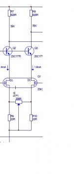
The trimpot to fix the offset is a way to go but did you try to match the input transistors first, secondly Q8 and Q9 and also Q3 and Q4 which is the current mirror.
Do a little measurement, what is the voltage between the collector and emitter leg of O11.
Attached I show picture of a trimpot setup to change offset but I would do some matching first as most of the time you should be able to get very low offset this way and not really need this adjustment.
When you measure the v between the resistor are you measering DC value. Make sure that your resistor values are correct according to schematics in these positions.
When you say you blew the amp did it blow playing loud music or did it go just by itself, youll have to check if the amp is not oscilating.
Check that you have the bias transistor connected correctly, meaning the the base collector emmiter legs are not swapped somehow.
The trimpot to fix the offset is a way to go but did you try to match the input transistors first, secondly Q8 and Q9 and also Q3 and Q4 which is the current mirror.
Do a little measurement, what is the voltage between the collector and emitter leg of O11.
Attached I show picture of a trimpot setup to change offset but I would do some matching first as most of the time you should be able to get very low offset this way and not really need this adjustment.
Attachments
Last edited:
Ok, all sorted now!!!
Fixing the dc offset works fitting a 100 ohm trimpot between R9, R10, R12, managed to get 2 mv dc output without matching the input transistors.
Bias fixed also. The problem was the bias transistor and the trimpot. I used BD139 and 500 ohm trimpot and i managed to adjust the bias. With 2SD2012 and 100 ohm trimpot I couldn't up the bias at all. With bd139 and 500R pot I managed to get 60 ma idle current. I left the amplifier at maximum bias for about 20 minutes and the output transistors barely warmed up, so did the preoutput transistors mje15032,15033.
All this was done with a +/- 40 V supply and 2n3055 mj2955 transistors.
I need to test the amplifier at higher rails and with several pairs of output transistors. I will try then to set the bias with 2sd2012 transistor to see if it works....maybe is suitable just for higher voltage.
At the moment I am playing some FLAC classical music and i can say the amplifier sounds very good. Mids and highs are crisp, clear and without coloration. Bass is punchy but I think this amplifier needs a low pass filter. Sometimes i noticed some really low frequency driver movements. I think is called subsonic filter. I will try to reduce the input cap from 10 mfd to something like 4,7 or 2,2. Can someone comment on the bandwidth of this amplifier? I know that C10 limits the high frequencies...in the original design it was 33pf but on the latest design which I received from author it is replaced with 470 pf.
Anny thoughts?
Thank you for the help homemodder!
I checked all the components and the board. All fitted ok ...no shorts on the pcb.
I measured voltage across Q11(BD139 now) collector and emitter and i got 2.4 volts with bias set to 30 ma.
When I blew up the amplifier I played music as loud as possible....after 3-4 seconds one of the outputs smoked and a fuse blew up.
What is weird is that all this happened on the positive side of the amplifier. The NPN transistor burned and the +v fuse blew up. And Q10, Q5 burned as well...I think Q10 burned first and Q5 when I re powered the amplifier to see if is alive.
Something weird. The preouts are getting slightly warm but Q12 on the positive rail is warmer than Q13....just a bit tho....maybe is just my imagination...I will try with a thermometer.
I checked all the components and the board. All fitted ok ...no shorts on the pcb.
I measured voltage across Q11(BD139 now) collector and emitter and i got 2.4 volts with bias set to 30 ma.
When I blew up the amplifier I played music as loud as possible
....after 3-4 seconds one of the outputs smoked and a fuse blew up.What is weird is that all this happened on the positive side of the amplifier. The NPN transistor burned and the +v fuse blew up. And Q10, Q5 burned as well...I think Q10 burned first and Q5 when I re powered the amplifier to see if is alive
. Something weird. The preouts are getting slightly warm but Q12 on the positive rail is warmer than Q13....just a bit tho....maybe is just my imagination...I will try with a thermometer.
- Status
- This old topic is closed. If you want to reopen this topic, contact a moderator using the "Report Post" button.
- Home
- Amplifiers
- Solid State
- Evens C-500 amplifier ....opinions?