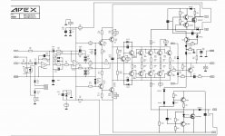
yes QQ12e5k1 made this and i build this to prove and share that this is a working circuit,
because nobody wants to try or share their experience with this schematic.

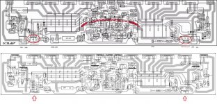
hi remele114,
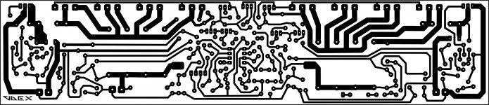
which layout is correct?
top or bottom?
Attachments
Maybe this would help?hi remele114,
which layout is correct?
top or bottom?
Attachments
hi remele114,
which layout is correct?
top or bottom?
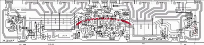
the one at the bottom is the correct layout
the one at the bottom is the correct layout
thanks remle for the reply,
is this amp stable?

Hello Nazirdigi ,
here is the corrected layout, change negative side marked 12k to 1.2k
thanks vedmitraa,
is this amp stable?
when clipping how many ac volt reading in dmm?
Hello Nazirdigi ,
here is the corrected layout, change negative side marked 12k to 1.2k
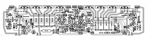
Would you two post the bottom layout,pcb for me? I have this scheme but i don´t have any other files...hi remele,
little edited to my taste.
Would you two post the bottom layout,pcb for me? I have this scheme but i don´t have any other files...
HERE IT IS.
Attachments
")

h900
Hi , also from me a happy birthday.
My problem is i had much work to do so only now I am back to my project , could someone please tell me what could be the problem when testing the amp with sine waves and watching the output at little input level everything works ok. No distortion no problems, the outcoming signal looks without distortion and so but when turning the input level up to say about 0.6 or higher volts the output transistors stage opens fully up and the transistors are blown but not the fuse which is like originally asked 15A.
I have my ideas what could be wrong maybe you could give me yours?
Thanks.
Are you using an oscilloscope to "look" at the output?................when testing the amp with sine waves and watching the output at little input level everything works ok.................. the outcoming signal looks without distortion and so but when turning the input level up to say about 0.6 or higher volts the output transistors stage opens fully up and the transistors are blown but not the fuse which is like originally asked 15A............
How long do you "test" at the higher output levels?
How hot do the output devices get?
Maybe the 15A fuse is too big.
900W into 4r0 is equivalent to 60Vac and 15Aac. The supply rails should be fused at about 7A or 8A. The output rail to the speaker could be fused at 15A.
But those fuses will take seconds to blow, if you overload the amplifier. During those few seconds the output stage and the drivers will have blown. Semiconductors fail a lot faster than fuses !!!!!!!!
- Home
- Amplifiers
- Solid State
- 900W H-class PA Amp with Limiter