U can use this diode on H900 V2 PCB.apex
can i use D5LC20
this is 3 pin dual diode ultra fast
16 a 200v prv
Yes, I will post schematics soon.apex
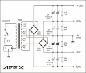
5 terminal must be from transformer the center must be ov,terminal 1,2,4,5 must be the x-former 4x40v
the other four terminal must be dc with discharge resistor,which is for +/-6o?and +/-120?
class h power supply
http://www.crownaudio.com/pdf/amps/grbgpapr.pdf
crown amp patented the class g
and qsc the class h
do they have the same psu?
http://www.crownaudio.com/pdf/amps/grbgpapr.pdf
crown amp patented the class g
and qsc the class h
do they have the same psu?
900 watts
hi apexaudio
greetings thanks for power supply circuit have wound my torridal
transformer yesterday will post pictures making soft start circuit
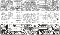
1 want to show you pcb with heatsink how i will mount it please tell me if it correct method and also your heat sink dimensions
thanks for your guidance and valuable suggestions
thanking you
andrew lebon
hi apexaudio
greetings thanks for power supply circuit have wound my torridal
transformer yesterday will post pictures making soft start circuit
1 want to show you pcb with heatsink how i will mount it please tell me if it correct method and also your heat sink dimensions
thanks for your guidance and valuable suggestions
thanking you
andrew lebon
Transformer 2500VA need soft-start.
can i use quasi's slow turn on/soft satrt ckt
Slow turn cct (Quasi's DIY Audio Site)
hi engel dela pena
greetings for soft start circuit go to rod elliots website in project page
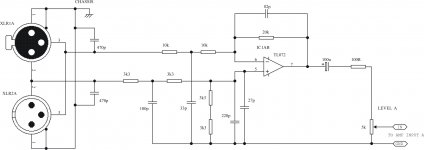
see soft start go to the circuit with the 8 pin ic no values are given the values are
1 ic 741 8 PIN DIP
R1 10 K
R2 1 K
R3 1 K
R4 10 K
R5 2.2 K
R6 1 K
TR1 BC 556
C1 470 UF 25 VOLTS
DIODES IN4007
R7 25 OHMS 15 WATTS OR 2 50 OHMS 10 WATT EACH IN PARALLEL
RELAY 12 VOLTS 10 AMPS OR GREATER
TRANSFORMER 0 9 1 AMPERE
C2 10 UF 40 VOLTS
THANKING YOU
ANDREW LEBON
greetings for soft start circuit go to rod elliots website in project page
see soft start go to the circuit with the 8 pin ic no values are given the values are
1 ic 741 8 PIN DIP
R1 10 K
R2 1 K
R3 1 K
R4 10 K
R5 2.2 K
R6 1 K
TR1 BC 556
C1 470 UF 25 VOLTS
DIODES IN4007
R7 25 OHMS 15 WATTS OR 2 50 OHMS 10 WATT EACH IN PARALLEL
RELAY 12 VOLTS 10 AMPS OR GREATER
TRANSFORMER 0 9 1 AMPERE
C2 10 UF 40 VOLTS
THANKING YOU
ANDREW LEBON
Who wants the big one? No one with any sense.
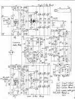
Yah I have seen this junk and it is so often a big smoky JOKE!! Start jerking the power supply rail around (called H or G) with a marginally stable amplifier and YES the smoke will come out!! Got a crappy Crown here in warranty blown up 3 times already. The amplifier that changes the supply voltage rail must be faster and ahead in time of the signal amplifier. Most of these rail voltage jerking amps have slow circuits jerking the rail around which never really does what it is supposed to do (in theory) so the amp goes unstable and blows its parts to wires or open circuits. Yah it is a nice idea but in the end it takes more parts to make it work than the equivalent higher voltage amp would. Further, the supply voltage rail jerking amp ALWAYS jerks the rail voltage on the last gain stage!! For all you theory specialist out there what happens when the rail voltage is jerked to a different voltage on the last gain stage? I shall kindly tell you, the transfer function of the amp changes so the feedback changes also and unpredictable gain and phase margin results. This mean smoke. Plus rail voltage jerking means kickback diodes cannot be used to prevent the output voltage from inductive kick back (never seen an inductive load with a power amp...NOT) from exceeding the lower power supply voltage rail which always causes output transistor degradation resulting in eventual smoke and wires where devices used to be. You want to jerk the rail voltage around? Use a real amp that is faster than the amp being rail voltage jerked. If this does not occur then the rail voltage jerking amp is likely to blow its little parts. Far better to use a ground referenced amp paired with a standard amp to get the voltage swing desired. I think Crown (macro reference) copied the Eagle 7, the most copied amp in the world, to make a ground referenced driving amp paired with a regular amp to achieve its bigger swing voltage. Eagle 7 schematic attached.
As another point, high power is interesting but WHY? I have yet to see a driver that can handle more than 34 volts RMS before increasing the voltage drive does not cause an increase in output. These lame amps have lousy damping when tested dynamically so more power does not make it louder--- only more distortion. Surely what is needed in PA work is more distortion, NOT! Further the idea that these wonderful designs provided by APEX AUDIO are needed to make a good PA is, is, is simply insane! 1000 watts is only 3 dB louder than 500 watts and 3dB is not jack. Far better to use an amplifier for every driver than to use a giant stupid unstable amp of huge proportion to attempt to achieve loud output with anything that resembles low distortion.
In the end an amp for every driver will completely blow away in sound quality and distortion any big stupid amp driving a bunch of drivers to insane power levels.
I greatly appreciate the effort by APEX AUDIO but the reality of PA system has been lost in the thought that bigger is somehow better. Let us focus on the fact that drivers to work within there somewhat linear region do not need that much power (34 volts RMS) to play as loud as they can before heinous and unsavory distortion drives me from the concert.
If the goal is to make noise and not music I have a 200 horsepower air compressor with a wideband modulatable orifice that will make like 175dB but then, who wants to listen to that? Keep the focus on BOTH low distortion with reasonable sound pressure level please and thank you.
Attachments
When you done first one in H class, you never come back on AB class for powerfull amps.
Regards Mile
every design has drawback,efficiency,realibility
building my first class h is a good experience
repairing of the same or other classes can make easier in the future
whoever is interested and to those who is not better not building this one but to those who is interested i'm sure there is fun and exitement upon building this class h
to apex thanks for sharing
If you jerk the rails around on EMITTER FOLLOWERS they don't usually do anything stupid. The amps can be made quite stable.
Who needs more than 34 volts RMS? No one. But let's see what it takes to get that "34 volts RMS". If you try to maintain any peak to average ratio, you need 10dB (otherwise it will sound like clipped compressed GARBAGE). That's a factor of 3.16 on voltage. So, 3.16 X 34 X 2^0.5 = 152 volts. Think you can get there on 80V rails? Bridge it, and generate more heat than the blazes of Hell and Damnation and you just might.....
Who needs more than 34 volts RMS? No one. But let's see what it takes to get that "34 volts RMS". If you try to maintain any peak to average ratio, you need 10dB (otherwise it will sound like clipped compressed GARBAGE). That's a factor of 3.16 on voltage. So, 3.16 X 34 X 2^0.5 = 152 volts. Think you can get there on 80V rails? Bridge it, and generate more heat than the blazes of Hell and Damnation and you just might.....
If you jerk the rails around on EMITTER FOLLOWERS they don't usually do anything stupid. The amps can be made quite stable.
Who needs more than 34 volts RMS? No one. But let's see what it takes to get that "34 volts RMS". If you try to maintain any peak to average ratio, you need 10dB (otherwise it will sound like clipped compressed GARBAGE). That's a factor of 3.16 on voltage. So, 3.16 X 34 X 2^0.5 = 152 volts. Think you can get there on 80V rails? Bridge it, and generate more heat than the blazes of Hell and Damnation and you just might.....
Your math is right of course but your thought is wrong. If the transducer goes into power compressing at 34 volts RMS the 152 volts is a complete waste! The point was POWER COMPRESSION sets in at 34 volts RMS and driving the transducer with more voltage only results in heinous distortion.
- Home
- Amplifiers
- Solid State
- 900W H-class PA Amp with Limiter