Hi all.
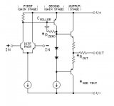
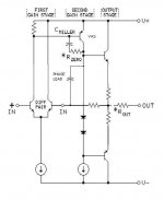
A Resistor with a Capacitor from collector to base of the second stage to create a unity gain stable amplifier.
This configuration VAS is good?
Why hardly any use RC compensation in VAS?
GEirin
JENSEN TRANSFORMERS, INC. - APPLICATION PAPERS AND SCHEMATICS
Some tips on stabilizing operational amplifier.
Attachments
you should read:
http://web.mit.edu/klund/www/papers/ACC04_opcomp.pdf
basically you need to know where to put the zero - which depends on output circuit, minor pole locations and output loading
power amps usually have slower output Q relative to the front end devices compared to monolithic ops so some relations aren't as clearcut
output loading is usually unspecified and varies between setups, other poles can move because of bias/output current changes
few diy amp designer/builders will have the equipment or knowhow to measure effectively at or above the loop gain intercept frequency
so simpler compensation that errs on the "safe" side with some reduced performance is usually preferred
Last edited:
Hi all.
A Resistor with a Capacitor from collector to base of the second stage to create a unity gain stable amplifier.
This configuration VAS is good?
Why hardly any use RC compensation in VAS?
GEirin
JENSEN TRANSFORMERS, INC. - APPLICATION PAPERS AND SCHEMATICS
Some tips on stabilizing operational amplifier.
Using the resistor in series with the Miller capacitor is something I have virtually always done. Where you put the zero is a matter of degree and good judgment. It should be done conservatively because the excess poles and excess phase you are using it to counter do move around with operating points, loads, etc.
I usually put the zero at least two octaves above the gain crossover frequency.
Getting the zero this way is, in my opinion, a much better way to get a zero than by placing a lead capacitor across the feedback resistor, since that can allow EMI from the speaker port to get back to the input stage.
Cheers,
Bob
Member
Joined 2009
Paid Member
Even the regular approach with a simple Cdom seems not so simple for the beginner (me).
I had fun with Cdom on the TGM amplifier, changing the value and listening to the sound. It had an interesting affect on the sound. Smaller Cdom around 15pF (still stable) produced something in the treble I didn't like, something a bit bright. Larger Cdom around 100pF took the life out of the music. But the goldilocks value, somewhere around 40'ish pF in my case was just the ticket.
I had fun with Cdom on the TGM amplifier, changing the value and listening to the sound. It had an interesting affect on the sound. Smaller Cdom around 15pF (still stable) produced something in the treble I didn't like, something a bit bright. Larger Cdom around 100pF took the life out of the music. But the goldilocks value, somewhere around 40'ish pF in my case was just the ticket.
- Status
- This old topic is closed. If you want to reopen this topic, contact a moderator using the "Report Post" button.
- Home
- Amplifiers
- Solid State
- VAS with Miller compensation zero