IMHO, the work involved to build anything so far exceeds the value of some 3055s that I'd go get some decent parts. They just aren't fast enough to do a good design and if you pair them up with an equally slow PNP there's a good chance of shorting out the power supply during full output high frequency testing. Some of those classic amps that used them were also known for their poor sound. Think power supplies and low frequency shaker table amps. 
Conrad
Conrad
You can put two 2n3055s in series to get higher rail voltages.
Hello
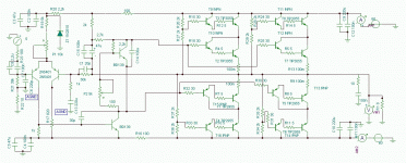
I've just finished, for a friend, to simulated an amp base on the DX amp and using 2n3055s in series and same for 2n2955s. I've post it in the DX thread.
After correcting an error the simulation work good.
It seem that my schematic can not have a suck-out capacitor between the drivers emiters, any ways to place a suck-out capacitor to reduce the driver switching noises ?
You would get about 125 watt out of this amp.
Bye
Gaetan
Attachments
Last edited:
You need to do a bit more work on th e fron t end of this design. THe output stages are slow, so you hav e to limit th e loop gain to giv e yourself some decent phase margin. 1st step her e is to provide some degeneration on that long taile pair. You hav e used a boot strap load on the VAS. While this is ok and gives good results, you might consider using a current source load (added bonus: use th e current source Vref to create a current source for the LTP - see Douglas Self for some examples on how to do this). For this type of classic design, I'd definietel;y encourage you to add a Zobel network and an output inductor.
good luck!
good luck!
You need to do a bit more work on th e fron t end of this design. THe output stages are slow, so you hav e to limit th e loop gain to giv e yourself some decent phase margin. 1st step her e is to provide some degeneration on that long taile pair. You hav e used a boot strap load on the VAS. While this is ok and gives good results, you might consider using a current source load (added bonus: use th e current source Vref to create a current source for the LTP - see Douglas Self for some examples on how to do this). For this type of classic design, I'd definietel;y encourage you to add a Zobel network and an output inductor.
good luck!
Hello
Yes, I would use a 100k hz low pass filter at the input and maby a CCS.
Maby also a phase lead capacitor. And a zobel.
And a better VAS transistor, like a 2SC3503
Any ideas where to put a suck-out capacitor ?
But that was a test schema and since I was using the DX amp as a base I did keep it close to the DX for now and to post it in the DX thread.
My friend will need to a prototype since I'm short of time to do it for him.
Thank
Bye
Gaetan
Last edited:
IMHO, the work involved to build anything so far exceeds the value of some 3055s that I'd go get some decent parts. They just aren't fast enough to do a good design and if you pair them up with an equally slow PNP there's a good chance of shorting out the power supply during full output high frequency testing. Some of those classic amps that used them were also known for their poor sound. Think power supplies and low frequency shaker table amps.
Sorry if I didn't mention before; I intend to use it as a subwoofer amp. Hopefully this clears a few things up. Besides, I have well over 25 pairs of each transistor; how many power supplies could I possibly need?
")
Thanks for all the info guys!
The last amplifier I built with the 3055/2955 had a power bandwidth of 230Khz, and it was a bit overcompensated.
The Carver M400 actually used the TO-220 3055/2955 as drivers on the top rail, and the selected metal case versions (MJ15015/16) for outputs. The low rail on the M1.5 used one pair of the MJ15024/25, and could drive 600W/4R.
I have a bunch of glorified 3055/2955 laying around (MJ15015/16), and some MJ15024/25 as well. I may have to knock a nice junk-box sub amp together too.
Tate modern
Hehe
I still thort the idea of a modern art masterpiece had merit -- you dont have to buy transformers and if it ended up in the Tate Modern Gallery - you could potentially get $1,000,000 for it
Still - you could also do it all at once -- use all of them in one sub amp with a 3KVA transformer to push a 6x18" JBL sub box around that wouldnt be out of place at a Pink Floyd Concert.........................j/k
Hehe
I still thort the idea of a modern art masterpiece had merit -- you dont have to buy transformers and if it ended up in the Tate Modern Gallery - you could potentially get $1,000,000 for it
Still - you could also do it all at once -- use all of them in one sub amp with a 3KVA transformer to push a 6x18" JBL sub box around that wouldnt be out of place at a Pink Floyd Concert
.........................j/kThe aged old electrician
I know my "Transformer" squeak was prob-a-be-ly thought of as insane,
but after re-storing a small pile of SS guitar amps, like Vox, I was really Impressed with how the Vox SS amps have great big tone bass, and are so simple to build, like twenty parts, maybe two hours work.
When we used to test these early Cerwin-Vega PA amps, with like twenty output transistors and one big driver transformer, we had a "shield" like a bomb test spot that had a remote power switch as these early amps had about 50,000 MFD on either rail!
So we would hook all up, and go hide in the "Remote Room" and fire it off....
Anyway, I am a fan of the old school circuit also because I go my hands on a pile of the Fender SS amp stuff, and built a # of 100-watt amps, some driving four-tens with "Germ" outputs that really had that Marshall sound.
I also worked on Gary Sunda's amps. He became Randall's engineer, but before that made heads using "Germs" and the old driver trans circuit, great smooth overdrive and pretty stable.
If the 2n3055s were used in some sort of Differential topology, could you get more slew rate???
Hey guys, I'm still hunting around for a design to build off of; I haven't quite abandoned this potential project yet.
I've done some reading but I'm still confused about connecting transistors in parallel; does it yield more output power or does it simply distribute the current among the transistors?
I've done some reading but I'm still confused about connecting transistors in parallel; does it yield more output power or does it simply distribute the current among the transistors?
Transistor Sister
You get more power
When a transistor is turned on, it has a resistance, so if you add more in parallel, then that resistance from collector to emitter goes down, so more current to the speak. (Conductance)
Current flow from the driver being the same
If you have them in series, then more voltage can be applied at the rails, and more current to the speak.
Transistor circuits can be pretty demanding brain wise.....
Tubes simple stuff....
I've done some reading but I'm still confused about connecting transistors in parallel; does it yield more output power or does it simply distribute the current among the transistors?
Paralleling outputs divides the current between each, improving safe operating area (SOA) meaning you can drive a lower impedance load without burning out your devices. Power is voltage and load dependent, the higher the voltage, the more potential power to the load. The lower the load impedance, the more current drawn for a given voltage equals more power also.
Hello
I've just finished, for a friend, to simulated an amp base on the DX amp and using 2n3055s in series and same for 2n2955s. I've post it in the DX thread.
After correcting an error the simulation work good.
It seem that my schematic can not have a suck-out capacitor between the drivers emiters, any ways to place a suck-out capacitor to reduce the driver switching noises ?
You would get about 125 watt out of this amp.
Bye
Gaetan
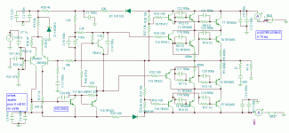
You're making it a bit more complicated. Use one driver for each parallel pair of outputs, not one for each. Then you only need two sets of divider strings and a lot less holes in the PCB.
You can't put a large suck-out cap on the outer set of drivers because it will upset the voltage division for fast rise signals. The inner set can have a standard suck out cap. One thing you can do is to put a resistor between the emitters of the outer driver transistors (maybe 20k) to force a higher bias current in the outer drivers. I did this on a 1500 watt amp of this style and it improved both crossover distortion and stability.
Hello
I've done another one and use the second type of suck out cap by placing it across the base stopper of all the output transistor. I've also raise the divider resistors value and put a buffer to the vas.
Thank
Bye
Attachments
If you are still interested, let me suggest you use them for what they can do well.
Forget 400/500W amps , although I *have* commercially built a lot of 400W ones .
But they were 400W into 1 ohm Bass Amps ...
I have built over 10000 (yes, not a typo, ten thousand) Musical Instrument amps since 1969, and of course used them for ages, since there was nothing else readily available, way back then.
(And also used 741's )
I suggest you build as many as you wish 100W into 4 ohms amps, with +/-35V rails , 4 output transistors , minimum 2200uFx50V caps per rail, 4700uF each even better.
Instead of a single 400/500W amp build a lot of powered boxes.
For PA, stuff them with 2x10" or 2x12" + 3 or 4 piezos + your 100W amp.
Add 2 input jacks in parallel for daisy chaining at will.
You can use 1 box in the garage, 2 in a small club, 8 or 15 per side in a live outdoors situation.
A very flexible setup.
A single box can be driven straight from keyboards; 1 or 2 can, with a switch which cuts tweeters off, boost power for any good but small Guitar or Bass amp.
I sold tons of such powered boxes, they are very useful.
Stopped using 2N3055 around 2008, because the counterfeit situation got unmanageable, but continued with TIP142/147 , which are about the same, with the driver transistor built-in.
Yet last week delivered a 200W into 2 ohms bass amp, to finish my once huge stash of 2N3055 ST.
It was accompanied by a 2 ohm, 4x10" speaker box.
So, in a nutshell, I actually *do* what I preach .
Forget 400/500W amps , although I *have* commercially built a lot of 400W ones .
But they were 400W into 1 ohm Bass Amps ...
I have built over 10000 (yes, not a typo, ten thousand) Musical Instrument amps since 1969, and of course used them for ages, since there was nothing else readily available, way back then.
(And also used 741's
)I suggest you build as many as you wish 100W into 4 ohms amps, with +/-35V rails , 4 output transistors , minimum 2200uFx50V caps per rail, 4700uF each even better.
Instead of a single 400/500W amp build a lot of powered boxes.
For PA, stuff them with 2x10" or 2x12" + 3 or 4 piezos + your 100W amp.
Add 2 input jacks in parallel for daisy chaining at will.
You can use 1 box in the garage, 2 in a small club, 8 or 15 per side in a live outdoors situation.
A very flexible setup.
A single box can be driven straight from keyboards; 1 or 2 can, with a switch which cuts tweeters off, boost power for any good but small Guitar or Bass amp.
I sold tons of such powered boxes, they are very useful.
Stopped using 2N3055 around 2008, because the counterfeit situation got unmanageable, but continued with TIP142/147 , which are about the same, with the driver transistor built-in.
Yet last week delivered a 200W into 2 ohms bass amp, to finish my once huge stash of 2N3055 ST.
It was accompanied by a 2 ohm, 4x10" speaker box.
So, in a nutshell, I actually *do* what I preach
.- Status
- This old topic is closed. If you want to reopen this topic, contact a moderator using the "Report Post" button.
- Home
- Amplifiers
- Solid State
- TIP3055/2N3055 based power amps