hi guys,
need opinions,
I recently use solid state Class A single ended mono with 1 mosfet 2sk1058 builded from DIY AUDIO PROJECTS - Do-It-Yourself Hi-Fi for Audiophiles = Mark housten.
but it's diffucilt to drive my 2 way bookshelp Dayton 6,5" 8 ohm.
if i put another same mosfet to be parelell, the power wil be up, but some people said the quality will be down, or just put another P-mosfet to be pushpull, but the quality will be down, it's that true ?
any suggestion ?
my travo 5 A : the 2'nd= 15 v, 3'rd= 12v or 6v ( i nust check it again),
can modified to hybrid or buffer with us tube 2c51 ?
thank's anyway guys !
Resistive loading is hugely inefficient... a constant current source would be much better.
Also the on resistance of a lateral FET is high and variable device to device, so that's another large loss... the Hitachi and Exicon data sheets claim a max saturation voltage of 12 volts at max drain current... no minimum or typical value is specified.
I think you would be lucky to see even a 10% efficiency on this circuit.
The article says the 15 ohm load resistor dissipates 30 watts at idle.
Quote "These get extremely hot and burn about 30W at idle"
What happened to ohms law") 12 volts across 15 ohms (at idle) isn't 30 watts.
12 volts across 15 ohms (at idle) isn't 30 watts.
Also the on resistance of a lateral FET is high and variable device to device, so that's another large loss... the Hitachi and Exicon data sheets claim a max saturation voltage of 12 volts at max drain current... no minimum or typical value is specified.
I think you would be lucky to see even a 10% efficiency on this circuit.
The article says the 15 ohm load resistor dissipates 30 watts at idle.
Quote "These get extremely hot and burn about 30W at idle"
What happened to ohms law
12 volts across 15 ohms (at idle) isn't 30 watts.It is a close to lousy design. With low efficency, extremely high distortion and very high Zout.
Build a Zen-style amp if you want a single transistor design that works.
If you want to build a hybrid use a tube like 6N6 or 6H30 with a MOSFET source- follower.
You can count on at least 10% THD at 1W. Assymetric (-4/+8V peak)clipping just above that at 20% THD. Zout 20hm. Using a IRFP240 will be better but still at least 5-6% THD at 1W out.
I built the ZCA and enjoyed it in spite of these things.
hi guys,
need opinions,...
You might want to check out this article from Nelson Pass. In it he also uses a single mosfet.
http://www.diyaudio.com/forums/diyaudio-com-articles/160464-de-lite-amplifier.html
similar to modified ?
guys, any particular schema to modified but with most similiar part on my project know ?
I built the ZCA and enjoyed it in spite of these things.
You might want to check out this article from Nelson Pass. In it he also uses a single mosfet.
http://www.diyaudio.com/forums/diyaudio-com-articles/160464-de-lite-amplifier.html
guys, any particular schema to modified but with most similiar part on my project know ?
Resistive loading is hugely inefficient... a constant current source would be much better.
Also the on resistance of a lateral FET is high and variable device to device, so that's another large loss... the Hitachi and Exicon data sheets claim a max saturation voltage of 12 volts at max drain current... no minimum or typical value is specified.
I think you would be lucky to see even a 10% efficiency on this circuit.
The article says the 15 ohm load resistor dissipates 30 watts at idle.
Quote "These get extremely hot and burn about 30W at idle"
What happened to ohms law
but there is no distorsion, very clean & live n tonal balance are good, typical class A, there only problem is hard to drive 2 way bookshelf 8 ohm !
Mark said: the amply burn 60 watt but only get pure 2-5 watt !
I built the ZCA and enjoyed it in spite of these things.
You might want to check out this article from Nelson Pass. In it he also uses a single mosfet.
http://www.diyaudio.com/forums/diyaudio-com-articles/160464-de-lite-amplifier.html
can i use the 2'nd 15 v and 3'rd 12v to drive tube 2c51 to be buffer or preamp ?
Resistive loading is hugely inefficient... a constant current source would be much better.
Also the on resistance of a lateral FET is high and variable device to device, so that's another large loss... the Hitachi and Exicon data sheets claim a max saturation voltage of 12 volts at max drain current... no minimum or typical value is specified.
I think you would be lucky to see even a 10% efficiency on this circuit.
The article says the 15 ohm load resistor dissipates 30 watts at idle.
Quote "These get extremely hot and burn about 30W at idle"
What happened to ohms law
it better to make it push pull or be paralell class A ?
Sorry to say, but you must be fooling yourself about distortion. Or maybe you just use the amp in the 1W region. 5% will be acceptable if it is only 2nd order.
On the downside if you build a descent 1-transistor amp like Zen is the low Zin. But that can be helped using a cathodefollower with a high Gm tube before.
The technical explanation to what happens when you add local feedback(drain to gate) to a FET is that the device goes from pentode-like behaviour to triode-like. This is the old Schade in action again.
None of them will help without local feedback. Especially parallell as this doubles the already very high input capacitance.
What you should do if you want a really low distortion hybrid is to go sourcefollower(100% feedback) with the MOSFET and let the tube handle all gain. You can then reuse most of your parts and doesn´t need to do much changes. 6N30P or 6N6P are good candidates. Will do a schematic and publish when I get home.
2C51 might have to high Ri to work. You will also need a separate HV-source for the drivertubes.
On the downside if you build a descent 1-transistor amp like Zen is the low Zin. But that can be helped using a cathodefollower with a high Gm tube before.
The technical explanation to what happens when you add local feedback(drain to gate) to a FET is that the device goes from pentode-like behaviour to triode-like. This is the old Schade in action again.
it better to make it push pull or be paralell class A ?
None of them will help without local feedback. Especially parallell as this doubles the already very high input capacitance.
What you should do if you want a really low distortion hybrid is to go sourcefollower(100% feedback) with the MOSFET and let the tube handle all gain. You can then reuse most of your parts and doesn´t need to do much changes. 6N30P or 6N6P are good candidates. Will do a schematic and publish when I get home.
2C51 might have to high Ri to work. You will also need a separate HV-source for the drivertubes.
Last edited:
thank's for uour kinf, Lars !Sorry to say, but you must be fooling yourself about distortion. Or maybe you just use the amp in the 1W region. 5% will be acceptable if it is only 2nd order.
On the downside if you build a descent 1-transistor amp like Zen is the low Zin. But that can be helped using a cathodefollower with a high Gm tube before.
The technical explanation to what happens when you add local feedback(drain to gate) to a FET is that the device goes from pentode-like behaviour to triode-like. This is the old Schade in action again.
None of them will help without local feedback. Especially parallell as this doubles the already very high input capacitance.
What you should do if you want a really low distortion hybrid is to go sourcefollower(100% feedback) with the MOSFET and let the tube handle all gain. You can then reuse most of your parts and doesn´t need to do much changes. 6N30P or 6N6P are good candidates. Will do a schematic and publish when I get home.
2C51 might have to high Ri to work. You will also need a separate HV-source for the drivertubes.
as i know 6N3 is a same character with 2c51 !
I really love the sound of class A ! hovefully yuor suggestion still on class A !
Hey there,
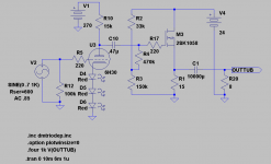
This a ruff sketch of the SF solution. It will still not be acceptable (in my eyes)as Iq is low). Running it at 40V/2A with a CCS and something like IRF240 would do the trick.
About 2C51 being close to 6H30, I think someone has missinformed you.
Ruff figures:
2C51 mu=35 S=5,5mA/V Ri=6,5kohm
6H30 mu=16 S=16mA/V Ri=1kohm
Attachments
tq
thank's Lars,
I will try ur schema ! can I push to use 2c51 ? because i got 6 !
Hey there,
This a ruff sketch of the SF solution. It will still not be acceptable (in my eyes)as Iq is low). Running it at 40V/2A with a CCS and something like IRF240 would do the trick.
About 2C51 being close to 6H30, I think someone has missinformed you.
Ruff figures:
2C51 mu=35 S=5,5mA/V Ri=6,5kohm
6H30 mu=16 S=16mA/V Ri=1kohm
thank's Lars,
I will try ur schema ! can I push to use 2c51 ? because i got 6 !
- Status
- This old topic is closed. If you want to reopen this topic, contact a moderator using the "Report Post" button.
- Home
- Amplifiers
- Solid State
- class A to Hybrid