I watched that video and I will try the method.what percent are acetone and alcohol that you used,if you tried this method, and what would be your "golden ratio"? I am very interested in this method, that's why i am curious about details...
(sorry for the off-topic...)
Cant use same layout /PCB for IRFP and 2SK/SJ. IRFP is GDS and latfets are GSD. You have to bend Transistor legs.I cant say if that can be done in your layout.
thanks friend... but i can fly wires.
Nice PCB... 70VDC is OK for 3 pairs.
Regards
Mr. Miles,
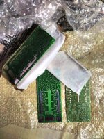
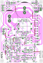
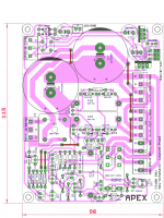
PCB for my layout, received from professional PCB supplier. Home etching is always a quick alternative
....Attachments
Mr. Miles,
PCB for my layout, received from professional PCB supplier. Home etching is always a quick alternative
Nice pcb, what about PSU and Protect?
Regards
Nice pcb, what about PSU and Protect?
Regards
Mr. Miles, making a layout for new fx100 psu... meanwhile i will try with another PSU that i have for the amplifier.
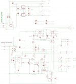
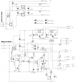
what needs to change on the Fx 100 PSU+protect for 70V rails? attached for reference.
Attachments
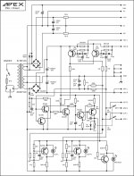
Use 10000uF/80V instead 63V.Mr. Miles, making a layout for new fx100 psu... meanwhile i will try with another PSU that i have for the amplifier.
what needs to change on the Fx 100 PSU+protect for 70V rails? attached for reference.
hi Mile.
it 's good dc protect for Apex CFA A33 ?
Grateful
Yes it is ok.
Regards
Yes it is ok.
Regards
Thank you Mr. Mile , will start A33
best Regards
Mr. Miles, making a layout for new fx100 psu... meanwhile i will try with another PSU that i have for the amplifier.
what needs to change on the Fx 100 PSU+protect for 70V rails? attached for reference.
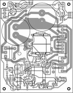
Here is the "quick and dirty" draft layout for New FX100 PSU as per the quoted schematic. It is compatible with schematic and with 18 mils min spacing.
Mr. Miles, can you confirm the schematic again, because I had significantly depart from old layout (more jumpers). Also kindly check relay connections.
I will keep improving it for reducing the jumpers and improving "symmetry"
.reg
Prasi
Attachments
Last edited:
Here is the "quick and dirty" draft layout for New FX100 PSU as per the quoted schematic. It is compatible with schematic and with 18 mils min spacing.
Mr. Miles, can you confirm the schematic again, because I had significantly depart from old layout (more jumpers). Also kindly check relay connections.
I will keep improving it for reducing the jumpers and improving "symmetry"
reg
Prasi
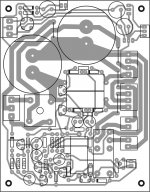
Nice work... this is FX100 PSU pcb without clip leds.
Attachments
Nice work... this is FX100 PSU pcb without clip leds.
Thanks. This is what I am looking for . are other component values same as FX100 PSU?
reg
Prasi
Thanks. This is what I am looking for . are other component values same as FX100 PSU?
reg
Prasi
Yes
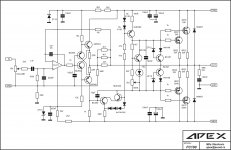
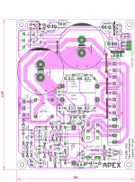
Mr. Miles, there was an error in FX100 PSU schematic shared . R9 (220k) does not connect to R15 (100k) in the layout shared by you two posts ago. Instead R15 (100k) connects to the junction of R18 and C13. I have it incorporated the changes in my eagle schematic . The schematic now corresponds to the layout shared by you.
attached are the schematic and layout. pl tell, if my layout is now ok, want to make PCB for it too.
reg
Prasi
Attachments
Mr. Miles, there was an error in FX100 PSU schematic shared . R9 (220k) does not connect to R15 (100k) in the layout shared by you two posts ago. Instead R15 (100k) connects to the junction of R18 and C13. I have it incorporated the changes in my eagle schematic . The schematic now corresponds to the layout shared by you.
attached are the schematic and layout. pl tell, if my layout is now ok, want to make PCB for it too.
reg
Prasi
it will be nice to have a Sprint file of this too
Best Regards
Juan
Mr. Miles, there was an error in FX100 PSU schematic shared . R9 (220k) does not connect to R15 (100k) in the layout shared by you two posts ago. Instead R15 (100k) connects to the junction of R18 and C13. I have it incorporated the changes in my eagle schematic . The schematic now corresponds to the layout shared by you.
attached are the schematic and layout. pl tell, if my layout is now ok, want to make PCB for it too.
reg
Prasi
Schematic is correct, I made error on my pcb.
Regards
Hi Juan,it will be nice to have a Sprint file of this too
Best Regards
Juan
I will correct the layout first as per the schematic and then post "eagle files " here. Dont have sprint!.
reg
Prasi
Hi Juan,
I will correct the layout first as per the schematic and then post "eagle files " here. Dont have sprint!.
reg
Prasi
Hi Juan,
as said, pl find the eagle files attached. I am sure you will make much better layout in sprint!
Mr. Miles,
how does the layout look now? ready for etching?
reg
Prasi
Attachments
Hi Juan,
as said, pl find the eagle files attached. I am sure you will make much better layout in sprint!
Mr. Miles,
how does the layout look now? ready for etching?
reg
Prasi
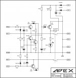
Corrected PCB.
Regards
Attachments
- Status
- This old topic is closed. If you want to reopen this topic, contact a moderator using the "Report Post" button.
- Home
- Amplifiers
- Solid State
- DC Servo MOSFET Amplifier