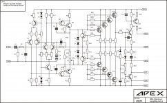
Simple Full Complementary Simetry +/-80V. Voltage amplifier/driver biased with 30mA. This driver circuit stabilized BIAS in output stage. Exelent stability without oscilation, hum and noise, sound great.
RMS Power: 240W 8ohm, 350W 4ohm
Go to post #470 for schematic and PCB
http://www.diyaudio.com/forums/solid-state/162043-mosfet-amplifier-irfp240-irfp9240-47.html
RMS Power: 240W 8ohm, 350W 4ohm
Go to post #470 for schematic and PCB
http://www.diyaudio.com/forums/solid-state/162043-mosfet-amplifier-irfp240-irfp9240-47.html
Attachments
Last edited:
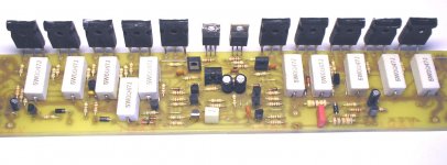
Circuit diagram work good even in PA amplifiers. I made over 120 PCBs in last 5 years. Beginer with basic expirience in DIY can easy made this amp. Usefull not only for hobby.
If you had used Lateral Mosfets in the output stage then i guess you could get away with such a simple biasing scheme. Lateral Mosfets have a negative temperature coefficient so they'll tend to reduce quiescent current as they heat up.
IRFP240 & it's complement have a positive temp coefficient (until they are drawing many Amps of current) so they'll conduct more current as they heat up. There is no allowance for this in your circuit diagram, you'd need something similar to what is used in a transistorised output stage.
I might be wrong, but i don't think so 😉
Bias stabilized with Q7,Q8,Q9,Q10. Q9 and Q10 are on same heatsink with output mosfets. This circuit stabilized bias even in PA use at the summer heat. This is not experimental schematics, uses over 10 years in amplifiers.
If you want to reduce distorsion significantly, you could add another set of transistors identical to Q8, Q9 connected to R11 in the same way Q8 and Q9 are connected to R10. The collector of the "new" Q9 connected to ground. The emitter of "new" Q8 connected to the old Q8.
And the same for the negative side. This way, the VAS is configured as a differential amp and is very likely to produce severly improved linearity. I will try this in my own amp soon, but the sims show very promising results.
🙂
And the same for the negative side. This way, the VAS is configured as a differential amp and is very likely to produce severly improved linearity. I will try this in my own amp soon, but the sims show very promising results.
🙂
Ok, im not doubting you 😉 Q9 & 10 are effectively emitter followers though, if you mount them on the same heatsink as the output transistors surely they can't compensate for quiescent on the output stage?Bias stabilized with Q7,Q8,Q9,Q10. Q9 and Q10 are on same heatsink with output mosfets. This circuit stabilized bias even in PA use at the summer heat. This is not experimental schematics, uses over 10 years in amplifiers.
Perhaps i'm having a stupid attack due to a few beers
 😀 My apologies if this is so...
Q9 and Q10 are not emitter followers, R21 and R22 in colectors Q9 and Q10 are in the same time in emiter Q7 and Q8.
I too doubt there will be adequate temp stability, but at 30 mA and a large enough heatsink it might not matter. The bias can increase somewhat, but the temp will perhaps stay within reasonable levels so the amp doesn´t go into thermal runaway.
If you had used Lateral Mosfets in the output stage then i guess you could get away with such a simple biasing scheme. Lateral Mosfets have a negative temperature coefficient so they'll tend to reduce quiescent current as they heat up.
IRFP240 & it's complement have a positive temp coefficient (until they are drawing many Amps of current) so they'll conduct more current as they heat up. There is no allowance for this in your circuit diagram, you'd need something similar to what is used in a transistorised output stage.
I might be wrong, but i don't think so 😉
You are right.
But, I found I could get away with a simple bias if I kept the bias current down to an absolute minimum.
I just barely bias the amp into none crossover distortion using a signal generator and a scope. Its suprising how little bias current you can get away with.
I think its peavey use a similar view of using a very low bias.
Last edited:
Q9 and Q10 run with 30mA, bias of the output tranzistor 200mA set by P1, and bias stay stabil. Maybie must corect after few minutes but that will be small corection.
Q9 and Q10 run with 30mA, bias of the output tranzistor 200mA set by P1, and bias stay stabil. Maybie must corect after few minutes but that will be small corection.
I found I could get away with 20mA on my design.
I then test by putting a household iron on the heatsink until it goes above 80 degrees c. I found it to be very stable despite not having bias transistor on output heatsink.
Actually, if D1-D4 have reasonable thermal contact with the output mosfets then they will stabilize the BIAS current, maybe just being inside the hot case might work. Not particular great, but might work in practice....
Q8 & Q12 need to have a diode, otherwise their intrinsic CB diode could be biased. Although it might not matter that much in PA applications....
And of course, the simple current limit should be made into a proper VI limiter.
Soren
Q8 & Q12 need to have a diode, otherwise their intrinsic CB diode could be biased. Although it might not matter that much in PA applications....
And of course, the simple current limit should be made into a proper VI limiter.
Soren
D1-D4 are 15V zener diode for protection not for bias. Once again I must replay this circuit is no experimental, amplifiers tested and uses over 10 years. Take a good look on this schematics again.


I would like to suggest on that current limit circuit a diode be placed in the collectors of Q12 and Q11. It is also nice to place a diode in the emitter of those same transistors.
D1-D4 are 15V zener diode for protection not for bias. Once again I must replay this circuit is no experimental, amplifiers tested and uses over 10 years. Take a good look on this schematics again.
You take a look again, Z1-Z4 are the zeners for protection.
D1-D4 are regular diodes, they have a negative temperature coefficient, basically lowering the current though the simple bias resistors when things heat up.... And you should be happy for that because otherwise you WOULD have had thermal runaway.
Again, not very stable or predictive, but apperently good enough....
Soren
I found I could get away with 20mA on my design.
I then test by putting a household iron on the heatsink until it goes above 80 degrees c. I found it to be very stable despite not having bias transistor on output heatsink.
I think you got it a little wrong , apexaudio is saying his mosfets are biased at 200 mA, the vas current is 30 mA, its quite high but thats why its a cfp vas.
I suggest anyone who want make upgrade on this circut is free to do it, and build new version. Original design work great for long time, and even beginer can easy build this amplifier. If you are beginer in DIY use my PCB design for first build.
I am sory for mixing diode, my mistake. When amp heating mosfet bias current litle lowering in fact.
This is PCB for protection. Use 2x18V AC for power. There are Soft-Start, DC, Overload and Thermal protect on 90deg. Two speed fan control 60deg (12V to 24V) when temperature heatsink is 60deg. Stabilized +/-15V for XLR and bridge input PCB. Temperature senzor is tranzistor BD241C.
Attachments

- Home
- Amplifiers
- Solid State
- MOSFET Amplifier IRFP240/IRFP9240