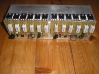
This PSU was used in time when I building this mosfet amplifier. There is PSU, DC and overload cut-out protect for each channel and soft-start for toroidal transformer. This circuit can be used with any amplifier.
how does overload cut-out protect works
thermal compensation
Actually , the thermal ~stability comes from D1,2,3,4, because the cross-over bias is dependent on VAS current which is a function of the diff-amp current, and one diode drop is across the current source(s) emitter resistor.
I'm not fond of completely symmetric front ends because there is so much bias dependency from one stage to the next and requires VAS emitter resistors. And according to some simulations I've done, there is no huge advantage in distortion that you would expect. And we know that symmetry cancels even order harmonics, which are "pleasant sounding", vs odd harmonics which are not. Harley Davidson sell a lot of motorbikes because the engine "defect" is very musical.
Years ago, Sinclair modules used a single resistor for cross-over bias and depended on the thermal compensation from the VAS current source, and that was a BJT circuit. Now, they blew up a lot because the output transistors were tiny and the system grounding critical, prone to oscillations. But they sounded great when they worked. That was my "previous life".
Ok, im not doubting youQ9 & 10 are effectively emitter followers though, if you mount them on the same heatsink as the output transistors surely they can't compensate for quiescent on the output stage?
Perhaps i'm having a stupid attack due to a few beers
Actually , the thermal ~stability comes from D1,2,3,4, because the cross-over bias is dependent on VAS current which is a function of the diff-amp current, and one diode drop is across the current source(s) emitter resistor.
I'm not fond of completely symmetric front ends because there is so much bias dependency from one stage to the next and requires VAS emitter resistors. And according to some simulations I've done, there is no huge advantage in distortion that you would expect. And we know that symmetry cancels even order harmonics, which are "pleasant sounding", vs odd harmonics which are not. Harley Davidson sell a lot of motorbikes because the engine "defect" is very musical.
Years ago, Sinclair modules used a single resistor for cross-over bias and depended on the thermal compensation from the VAS current source, and that was a BJT circuit. Now, they blew up a lot because the output transistors were tiny and the system grounding critical, prone to oscillations. But they sounded great when they worked. That was my "previous life".
This is my contribution to APEX HV250 amplifier, for those without prejudices about OP amp in front. Thanks Mr. Mile
Pozdrav
Pozdrav,
Thanks for giving me the link to this post from the main Apex thread. Did you switch to NE5532 as Djk suggested? Would you have Gerber files for this as I can’t home etch something this big.
Thanks,
X
Pozdrav,
Thanks for giving me the link to this post from the main Apex thread. Did you switch to NE5532 as Djk suggested? Would you have Gerber files for this as I can’t home etch something this big.
Thanks,
X
I used the IC original one. Sorry, I dont have gerber files because I did it in corel draw, but this is not so big.
using "paint" is OK,but it is very painful... try to use China PCB Prototype & Fabrication Manufacturer - PCB Prototype the Easy Way program or such of free one. it is much easier to use than paint. I use sprint6 and it is very helpful when you get used to it. there is no need to do it hard way nowadays...
Also, forgot to mention that I use mostly PowerPoint for quick hand layouts. Anything more complicated I leave to experts like JPS64 or Prasi.
Thanks for the tip though.
I also use Sharpie markers for very fast rough designs.
Here is the DLH Class A amp:
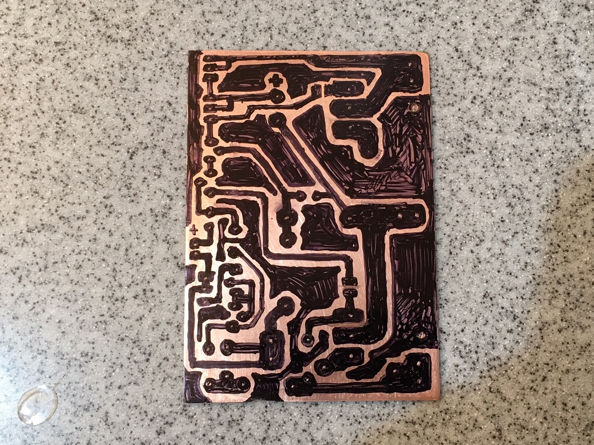
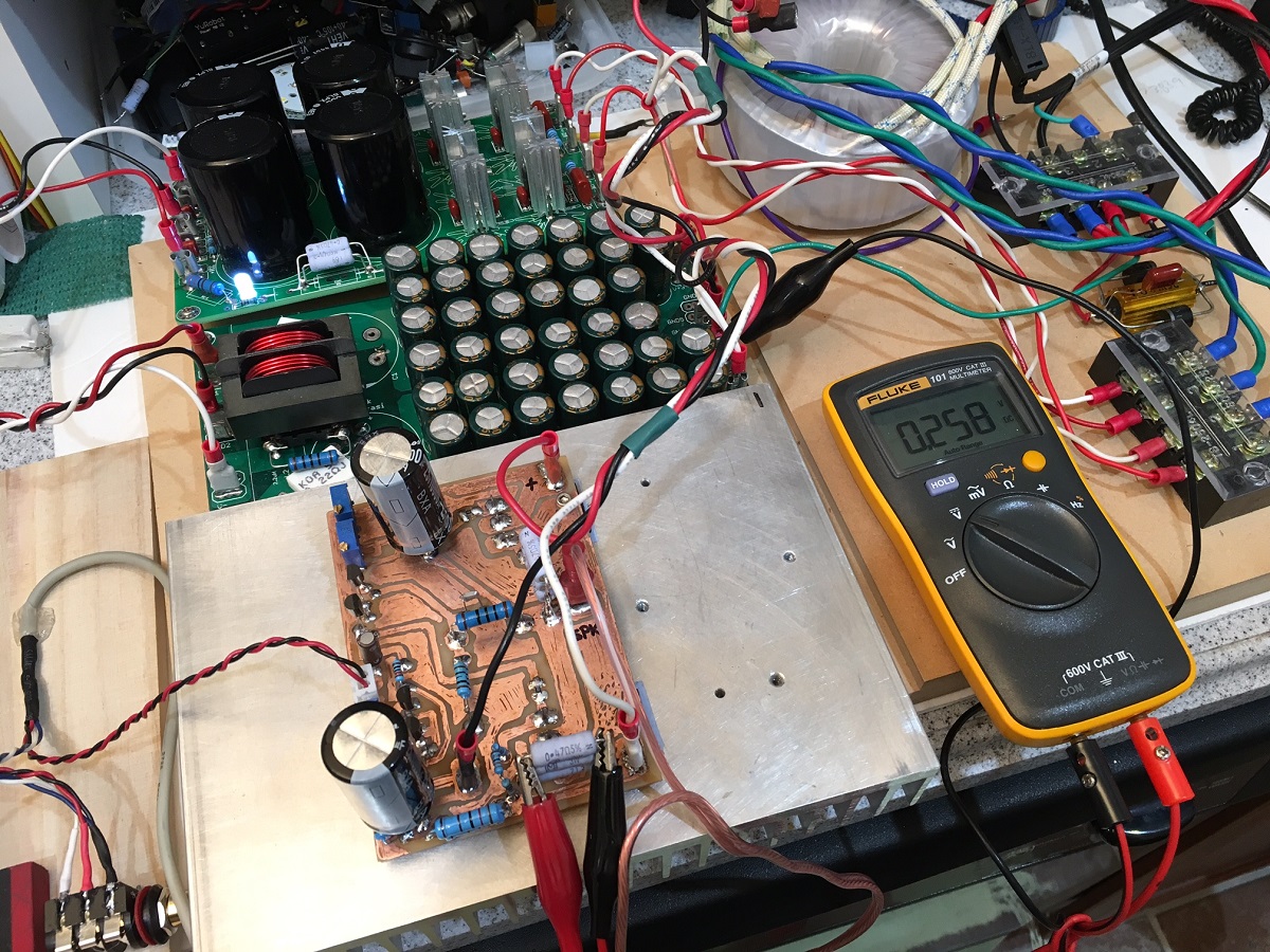
That amp was probably the highest bias current amp I have made with a Sharpie.
Thanks for the tip though.
I also use Sharpie markers for very fast rough designs.
Here is the DLH Class A amp:
That amp was probably the highest bias current amp I have made with a Sharpie.
Last edited:
using "paint" is OK,but it is very painful... try to use China PCB Prototype & Fabrication Manufacturer - PCB Prototype the Easy Way program or such of free one. it is much easier to use than paint. I use sprint6 and it is very helpful when you get used to it. there is no need to do it hard way nowadays...
With people giving away PCBCAD software there is little need for paint etc.
Also, with Chinese manufacturers giving away PCB's not much reason to make your own now.
JLCPCB $2 for 10 off 100mm by 100mm
PCBWAY $5 for 10 off 100mm by 100mm
Turn around time is usually just a few days, depends how much you want to spend on postage.
- Home
- Amplifiers
- Solid State
- MOSFET Amplifier IRFP240/IRFP9240