hi apex i want protection pcb layout and circuit for mosfet amp plz send me khalsaaudiocenter@yahoo.com
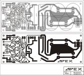
PSU for DIY with soft-start and DC protect. Transformer 1kVA sec: 2x55V 8A + 24V 1A.hi apex i want protection pcb layout and circuit for mosfet amp plz send me khalsaaudiocenter@yahoo.com
PCB size: 200x75mm
Attachments
You may look here http://www.diyaudio.com/forums/solid-state/162911-current-feedback-ic-input-power-amp.htmlCould you show schematic as a jpg image or other format that other users not having tina could see, Im interested in seeing this self biased cascoded.
This thread concerns a design that is is embedding the self-biased cascode VAS. There are schematics JPGs. However I advise you to download and run Tina 7 Texas Instruments.
Could you show schematic as a jpg image or other format that other users not having tina could see, Im interested in seeing this self biased cascoded.
I'm satisfied that simply adding 100uF to the original design pushes full output
single sine bandwidth to 91KHz, and sufficient slew to do that goes with. I'm
not sure its necessary or desirable to slew wider bandwidth than 96K???
Don't hold your breath, hoping I might translate the cascode variant to LTSpice.
Its a whole lot of extra part spaghetti, else requiring a new PCB layout. And I
simply feel it may be overkill fix for reasonable design compromises that aren't
causing any actual problems.
Ive seen it, I prefer simpler design myself, often I had found myself going off on complicated designs only to end up with a amp that does not sound any better and often worse, than a amp with half the parts.
BTW I did find the apex to oscilate in LTspice, at 20Khz, this is the frequency I always simulate or measure at.
You can use mine as a shortcut to get started, if you wish.I was planning to transfer the Tina circuit to LTSpice. I'll post it if / when I get around to it !
Don't take my doubts about needing a cascode to mean you
should have to start the translation over again from scratch.
Well, the 91kHz referred to the loop gain transition frequency, i.e. |LG(91kHz)|=1
This does not change with or without the 100µF, as I said the whole loop gain curve doesn't change.
But i guess it can be nice to have a good margin for slewrate.
Is that what you mean with "to slew a bandwidth of 96K":
The amp has the slew rate that is needed to reproduce a 96kHz sine wave at full output amplitude?
would be nice to know, because it was a nice, short and efficient way of saying that")
This does not change with or without the 100µF, as I said the whole loop gain curve doesn't change.
I don't think it is essentially necessary to have a slew rate greater than needed to follow a sine wave with maximum output amplitude and the highest frequency ever occuring in program material presented to the amp.kenpeter said:I'm satisfied that simply adding 100uF to the original design pushes full output
single sine bandwidth to 91KHz, and sufficient slew to do that goes with. I'm
not sure its necessary or desirable to slew wider bandwidth than 96K???
But i guess it can be nice to have a good margin for slewrate.
Is that what you mean with "to slew a bandwidth of 96K":
The amp has the slew rate that is needed to reproduce a 96kHz sine wave at full output amplitude?
would be nice to know, because it was a nice, short and efficient way of saying that
I tried 2VPP@96K in, and it looked good. No triangles. Just slightly attenuated.
Jumped on your 91KHz figure as the better number without actually re-checking.
I also did not test the circuit quite as close to the limit of clipping as I probably
should have. Thats not (yet) to say the result would have been any different.
I gotta be more careful not to casually throw numbers without stating exactly
how I arrived at them. Or in this case, just fudge factored it, based upon a
few sim runs aimed at determining something else entirely...
At the time of the test, I was obsessing upon output currents and how they
crossed (or didn't) at the higher frequency. As push and pull get phase shifted
away from each other till they don't cross nice (without 100uF cap in place).
Wasn't attempting at that time to scientifically determine actual bandwidth.
As for why 96K instead of 20K for a single sine? Was something one of the
forum gurus (Cordell? or was it Pass?) I don't remember now... Transient
intermodulation when you got 18K and 19K into the amp at the same time.
That somehow that slew rate challenge was like a single sine 96K? I never
checked the truth of that math. It sounded plausible, I went with it.
I should probably just sum two sines, if I wanna test TIM, rather than fake it.
Last edited:
Allright.
Interesting thing, these 18k+19k - haven't thought of that.
After all, one single sinewave doesn't seem to be a sufficient approximation to music, when it comes to such details.
I will have to think about that.
I might have a look at some band limited pink noise signals and what slew rate they might ask for... (hmm, I guess actual music might do the job as well)
but this is leading a bit off topic, maybe...
Interesting thing, these 18k+19k - haven't thought of that.
After all, one single sinewave doesn't seem to be a sufficient approximation to music, when it comes to such details.
I will have to think about that.
I might have a look at some band limited pink noise signals and what slew rate they might ask for... (hmm, I guess actual music might do the job as well
)but this is leading a bit off topic, maybe...
This PCB is still in comercial use, posted Power and Protect PCB with Soft-Start is compatibile with MOSFET AMP. This PSU PCB is for stereo amplifier.hi apex thanks for send the power suplly pcb layout but i want the layout of your 20 no fourm kindly send me
hi apex i am used this circuit for comercial audio kindly send me the circuit and pcb layout thanks khalsaaudiocenter@yahoo.com
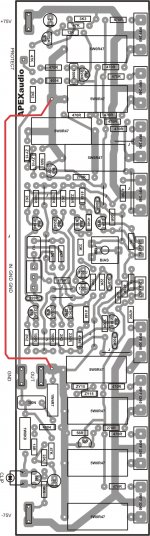
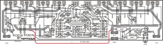
VI cut-out. Post signal to protect bord #122.hi apex what is the function off q 22,23
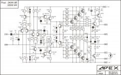
Simple Full Complementary Simetry +/-80V. Voltage amplifier/driver biased with 30mA. This driver circuit stabilized BIAS in output stage. Exelent stability without oscilation, hum and noise, sound great.
RMS Power: 240W 8ohm, 350W 4ohm
Nice work. I have something similar. http://www.diyaudio.com/forums/solid-state/154104-topology-federmann-hqqf-55-a.html
I will soon publish a detailed plan and the results of all measurements and tests. I have very many interesting results.
Thank you, but I see much diferent design.Nice work. I have something similar. http://www.diyaudio.com/forums/solid-state/154104-topology-federmann-hqqf-55-a.html
I will soon publish a detailed plan and the results of all measurements and tests. I have very many interesting results.
- Home
- Amplifiers
- Solid State
- MOSFET Amplifier IRFP240/IRFP9240