Terry, just two things.
Solder the separate signal gnd to power supply 0v, very critical.
If this isn't well contact the 50v rail is present on the output and a speaker short the output.
Second, what is the bias?
Higher than 100mV is danger.
Use your simulation program to find the max bias that is safe.
Mile, can you answer what is the max safe bias setting?
THD strongly depend from bias setting.
I will post results soon.
Hi Thimios,
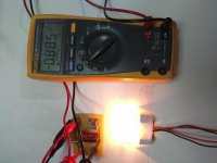
I have separate ground wires running back to the PSU for signal ground and power ground. They are only about 8" long but they are separate. I was running 150mA bias because anything lower than that and the offset was over 100mV. For the short time my signal generator was working I saw oscillation on the sinewave. I had been using a light bulb tester but had bypassed it once everything looked ok so I could run both channels with music through them. I now have to repair my FX100 PSU because of this amp. I'm not anxious to try this again.
How the bias setting affect the THD.
I will ask again.
Using +/-50v power supply.
What is the max safe value for bias setting?
For HexFETs recommended bias is at least 50mA. Some say 100mA is better. Although distortion is higher, I like the sound when bias is low 15-20mA. Max safe value depends on how big is your heatsink. Heatsink temp should not be higher than 50 degree Celsius.
For HexFETs recommended bias is at least 50mA. Some say 100mA is better. Although distortion is higher, I like the sound when bias is low 15-20mA. Max safe value depends on how big is your heatsink. Heatsink temp should not be higher than 50 degree Celsius.
Hi ian, i don't think so.
This amplifier haven't thermal stability resistors, no source resistors no drain resistors.
Any attempt to use higher bias than 250mA blow the Mosfets,regarless the size of the heatsink.
My Main problem is offset. I can't seem to get the offset to settle at a low value. Mains voltage changes it greatly. I have KSC3502 in now for the VAS. I haven't hooked up a speaker yet because of the offset. I know 70mV isn't a lot but I just think it should be able to go lower.
70mV isn't a problem.
I have just finished designing a class AB amplifier.
The dc offset starts off at -200mV but as the amp warms up it goes to zero.
The bias current moves around a bit too from 5mV to 15mV across the 0r22 output resistors. The Vbe multiplier transistor is next to the heatsink so it will drift as the heat goes up and down.
The bias can drift with the dc offset I found. As the dc offset goes up or down so the more/less bias current goes into speaker.
Hi ian, i don't think so.
This amplifier haven't thermal stability resistors, no source resistors no drain resistors.
Any attempt to use higher bias than 250mA blow the Mosfets,regarless the size of the heatsink.
If you want 250mA bias you must add 1R/5W source resistors.
static power dissipation, following the thermal dissipation curves for the devices, based on die temp.What is the max safe value for bias setting
you need a way to measure the current in the MOS200 design.
I do wonder why you want to make this design knowing all of its weaknesses?
Vertical mosfet need bias servo for bias current stability in class AB. IRFP240/9240 have Vgs temperature coefficient -6mV/C, according Bob Cordell's book. For class B, if safe without bias servo.
Crossover distortion of mosfet depend of bias current value. More bigger value, more less distortion. Bob Cordell advocate 150mA bias current, for good compromise between distortion and efficiency. But I like more than 150mA.
You can hear crossover distortion, if you set volume as minimum as you can, but you still hear the sound clearly. Pay attention in high frequency. But for trained listener, it can be notice crossover distortion at high SPL (Sound Pressure Level).
Last edited:
I have add a series resistor to positive power supply. Measuring the voltage drop you can set the bias. Short the resistor and play, nothing difficult.static power dissipation, following the thermal dissipation curves for the devices, based on die temp.
you need a way to measure the current in the MOS200 design.
I do wonder why you want to make this design knowing all of its weaknesses?
Mine is playing in stereo mode using cheap speakers. You must listen to this, then you will understand
")
Hi guys,
a tip, do I want to put the input potentiometers into the signal in these amps HV23 of mine to adjust the gain? what value and type?
Thank you
Nice work, use 10k/LIN
Nice work, use 10k/LIN
Grazie<<>thanks
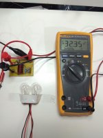
Testing Apex crowbar protection.
This will be used for cheap protection in mos 200.
You must add fuses in mos200 if you want use crowbar protection.
You must add fuses in mos200 if you want use crowbar protection.
Yes i know, there are fuses already in the power supply.
Vertical mosfet need bias servo for bias current stability in class AB. IRFP240/9240 have Vgs temperature coefficient -6mV/C, according Bob Cordell's book. For class B, if safe without bias servo.
Crossover distortion of mosfet depend of bias current value. More bigger value, more less distortion. Bob Cordell advocate 150mA bias current, for good compromise between distortion and efficiency. But I like more than 150mA.
You can hear crossover distortion, if you set volume as minimum as you can, but you still hear the sound clearly. Pay attention in high frequency. But for trained listener, it can be notice crossover distortion at high SPL (Sound Pressure Level).
That's not my experience with 240/9240.
I set the bias using sig gen and scope.
Connect speaker and turn up bias slowly until cross over distortion just goes on the scope. I find the bias current is usually in tens of milliamps rather than hundreds. The amp sounds fine this way and less power wasted as heat.
Peavey are great advocates of low bias currents.
bimo, a good amp can visually (scope) make crossover distortion virtually disappear at 3.5 to 4v of bias. Valery measured the crossover distortion of IRFP240,9240 to be 0.005% at 100ma bias.
Revisiting some "old" ideas from 1970's - IPS, OPS
Revisiting some "old" ideas from 1970's - IPS, OPS
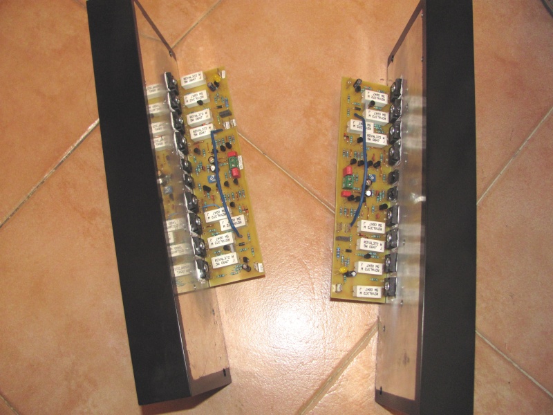
OK, I wasn't satisfied that I had everything right so I etched a new set of boards and started over with all new parts. This is what I have now. First of all, I can get it to adjust to 20mA bias and the 100k pot will adjust the offset to 0V. It will play music one channel at a time but it sounds a little distorted. It will not work with both channels hooked up to the PSU. As soon as I do that, the bias goes through the roof. Fortunately I have it hooked up via a light bulb so nothing burned up this time. The only thing I have done different that the schematic is that I used 47n rather that 56n, 4k7/4k7 rather than 6k8/6k8. I also used KSC3503 for the VAS and BD139 for the bias spreader.
Looking for suggestions.
Looking for suggestions.
- Home
- Amplifiers
- Solid State
- MOSFET Amplifier IRFP240/IRFP9240