While I was at school I noticed in our stock room we had a bunch of really old germanium transistors. Most of these were General Electric (From GE-01 onward). Anyway, after liberating two of the power transistors (Max rating being 50v, 12 amp) I wanted to build an all germanium power amp.
Using one would use a push pull design with pnp/npn transistors but I couldn't find any npn transistors so I opted for a Direct Coupled design.
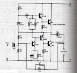
So far I have a basic layout using FETs to get the signal out of phase and insert those into the transistors. All I need help on is anything major that needs to be done (values in the power stage, anything missing). The pre-amp stages are going to be Germanium, FET and Tube based and are pretty easy to implement so no worries on that part.
Here is what I have so far, any help would be appreciated.
Using one would use a push pull design with pnp/npn transistors but I couldn't find any npn transistors so I opted for a Direct Coupled design.
So far I have a basic layout using FETs to get the signal out of phase and insert those into the transistors. All I need help on is anything major that needs to be done (values in the power stage, anything missing). The pre-amp stages are going to be Germanium, FET and Tube based and are pretty easy to implement so no worries on that part.
Here is what I have so far, any help would be appreciated.
Attachments
Hi
I'm not really familiar with germanium but the input stage doesn't look too healthy.
The upper output device (Q1) needs much more voltage swing on it's base than the lower one. Also - how high is the current gain of those germaniums? You've only got about 1mA available to drive them.
Mooly's building a germanium amp here:
http://www.diyaudio.com/forums/headphones/160646-germanium-single-ended-class-headphone-amp.html
Presumably he understands germanium and might be able to help.
Cheers - Godfrey
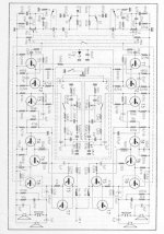
You have two main options: you take the schematic of a quasi complementary amp of the seventies, and you change the polarity of all transistors (and adapt the base bias network), or you use an original Ge schematic.
Here is an example from Loewe, 20W /ch intended initially for AD150 devices:
Here is an example from Loewe, 20W /ch intended initially for AD150 devices:
Attachments
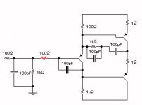
Dasruckus, you need to look at the classic Lin circuit ")
I'm afraid your circuit would never work... first the leakage of germanium would swamp the front end... you need far more drive current too. Bias ?? crossover distortion ?
The Linn circuit is where all modern amps started in a way. You could elaborate it as much as you want... DC coupling, differential input etc
The outputs are in a quasi complementary arrangement allowing two PNP's to be used. You still need an NPN device as driver though... or FET's.
Some devices are still available from certain sources if you are really keen.
Attachments
All I did was derive what I could use from older designs, such as this one and instead of using a transformer to get the signals out of phase I just used FETs based on a tube design. I really want to keep it simple but is there really no other way besides what has been posted?
Attachments
Dasruckus, you need to look at the classic Lin circuit
I'm afraid your circuit would never work... first the leakage of germanium would swamp the front end... you need far more drive current too. Bias ?? crossover distortion ?
The Linn circuit is where all modern amps started in a way. You could elaborate it as much as you want... DC coupling, differential input etc
The outputs are in a quasi complementary arrangement allowing two PNP's to be used. You still need an NPN device as driver though... or FET's.
Some devices are still available from certain sources if you are really keen.
I don't understand the theory of operation from this circuit.
Only when I reverse the polarity of the supply voltage, the circuit works by simulation.
I don't understand the theory of operation from this circuit.
Only when I reverse the polarity of the supply voltage, the circuit works by simulation.
Typo error
negative rail of course, and using a "positive" earth.All I did was derive what I could use from older designs, such as this one and instead of using a transformer to get the signals out of phase I just used FETs based on a tube design. I really want to keep it simple but is there really no other way besides what has been posted?
Not really... the driver transformer in your example matches and provides a current (relatively speaking) base drive to the outputs. Remember tubes are essentially "voltage driven" unlike Bjt's
You need something like the quasi complementary output stage as in the Linn etc and develop it from there.
There is no reason why a driver stage constructed from N and P channel FET's couldn't be used too.
Why not go with the transformers? They're not that bad, and still seem to be available e.g. Miniature Drive Transformer (ANB91G) [ANB91G] - R26.95 : Zen Cart!, The Art of E-commerce
OK, wrong country, but if I can find them even here they must be available where you are.
Heck, if you're doing "retro", you may as well go the whole hog!
Or if you're shooting for maximum diversity, you could always drive the geraniums with opamps (with a valve input stage, of course)
Having a handful of those things sounds like a recipe for fun, whichever way you decide to go. (unless you start taking it seriously, of course)
Cheers - Godfrey


- Status
- This old topic is closed. If you want to reopen this topic, contact a moderator using the "Report Post" button.
- Home
- Amplifiers
- Solid State
- Germanium Power Stage Amp - help needed