ok .... now you have to be nice to me please
i am no good with tubes and i am no goot with mosfets .....as my avatar say i am a 2SA1302 guy
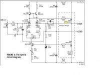
so i have a load of 12AU7 tubes and a load of J352-K2221 mosfets ....so i found schematics in the internet for hybrid amplifiers like the one posted
----is this combination going to work ???
----is this an amplifier worth buliding ???
---- then again under the specific material is there any changes to be made ???
opinions please and some help
it will be a waste to have all these goodies unused
i am also open to other circuits so everything is welcome
thanks sakis
i am no good with tubes and i am no goot with mosfets .....as my avatar say i am a 2SA1302 guy
so i have a load of 12AU7 tubes and a load of J352-K2221 mosfets ....so i found schematics in the internet for hybrid amplifiers like the one posted
----is this combination going to work ???
----is this an amplifier worth buliding ???
---- then again under the specific material is there any changes to be made ???
opinions please and some help
it will be a waste to have all these goodies unused
i am also open to other circuits so everything is welcome
thanks sakis
Attachments
Hey Sakis,
ECC82 is a very unlinear tube needing feedback to work well.
To get the most of it you shoud go for something like 10mA/120-150V. Ie as Zen Mod states, it is not suitable here.
Maybe you can use it as input-device in a folded cascode driving an outputstage.
ECC82 is a very unlinear tube needing feedback to work well.
To get the most of it you shoud go for something like 10mA/120-150V. Ie as Zen Mod states, it is not suitable here.
Maybe you can use it as input-device in a folded cascode driving an outputstage.
Last edited:
guys ....come one .... be with me now
i dont have neither ECC 88 nor ECC82 i have 12AU7 !!!! all of these work diferent and here is were i need help
then again i am not looking for a headphone amp and also the above schematic is something similar to elektor schematic that was published and working
i dont have neither ECC 88 nor ECC82 i have 12AU7 !!!! all of these work diferent and here is were i need help
then again i am not looking for a headphone amp and also the above schematic is something similar to elektor schematic that was published and working
12au7=ecc82
i am sorry i think that this is not correct ...12AU7 is similar to ecc82 but not the same
then again if i am wrong and these tubes are the same what about the rest of the circuit ( since its supposed to be copy of the working elektor circuit )
and also what about my mosfets ???? are these mosfets switable for this application ????
regards sakis
Q1 and Q2 are drawn wrong and additionally are npn on the drawing. They should be PNP . Q4 is also incorrectly drawn .The type numbers however are correct. You plan to use IRF9540 and IRF540 ...correct ?
You need to have a relay to connect to the headphones. While power up and down the output voltages can swing up to the supply voltage causing some damage or destroying the phones .
Why don't you sim the circuit and see what you get. However as the 12AU7 ( ECC82 ) is not very linear the way you want to use it ,even if you can get distortion figures down, it might not sound as clean ( very subjective) as an inherently linear tube like the 6DJ8 or 6922 . But then you might never notice the difference unless you compare them side by side. If you just have the
12AU7 just go ahead and build one using it. Don't forget to use a delayed relay switch on and instant disconnect on power down. Or just plug in phones after 30 seconds or so after power on and disconnect phones before power down.
OR for testing use a back to back 470uF caps between phones and amp. That will protect it from dc . If they are good caps it might not be too audible in the signal path. I've found some Samwha elco's quite decent.
Last edited:
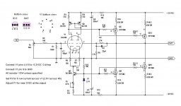
Can't find the more recent drawing I was wanting to post, but this is close.
I think the only difference, I had a +/- supplies and servo details completed
in the other... In newer version the output cap would not be needed. I'll
keep looking for it, its probably on my other PC.
Maybe an outside the box idea?
Here we see 50% UL feedback into the 12AU7 plate.
I've never built it, only sim. But in sim, this trick seems to work just fine.
I think my reasoning for the 50% plate swing was to keep the plate
voltage from dipping too low, but still allow a full voltage output.
M1 then has a synthisized Mu twice that of the feedback triode.
Its been a long time to remember all the details.
Attachments
Last edited:
Ah, here it is....
The Servo is MJK style. And my Anti-triode active load in the
upper right corner of both drawings, is roughly based upon
Nelson Pass' Aleph.
The collector of Q2 could probably go straight to -25 and
eliminate R11,R12,C5. The lower end bootstrap might have
been pointless leftover of some earlier thought process?
Attachments
Last edited:
- Status
- This old topic is closed. If you want to reopen this topic, contact a moderator using the "Report Post" button.
- Home
- Amplifiers
- Solid State
- 12AU7 + mosfets