Omtec Mono Power Amplifier "CA-25"/"CA-60" (CA25/CA60) - Schematic wanted
For this mono block device I need a schematic diagram. There isn't a download aera for PDF schematics. Only for the Owner's Manuals of all models
Bedienungsanleitungen
and I have heard, that no schematic would be released (like Krell Industries).
So I must hope, one of the members have an own created schematic
If so, please let me know - thank you very much
Attachments
Last edited:
schematics available there (also for CA60):
Gebrauchte HiFi Geräte kaufen - Spring Air Second Hand HiFi Shop
http://www.springair.de/bastlergeraete/endverstaerker/39209/omtec-ca-25-mono-endverstaerker
Unfortunately, this will not be sent to user's - they are only used to repair there.
After all, there is now an address for repair and cost estimate of this amp models.
Hi,
habe gerade mit springair telefoniert. Schaltpläne sind zu 99% vorhanden???? Jedenfalls kein Commitment.
Mein Problem: Meine Ca25 V1 werden ungleich warm. Ich würde gerne den Ruhestrom einstellen. Wo liegt der Zielwert?
Manni Baier ist unter der Nummer, die google findet nicht erreichbar. Ich würde auch gerne seinen Service in Anspruch nehmen. Kann mir jemand weiterhelfen? Evtl. auch mit Schaltplänen, Abgleichanleitungen??? Mannis Telefonnummer per PN wäre auch attraktiv.
Danke.
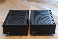
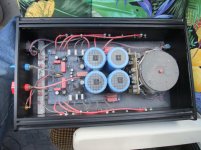
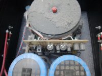
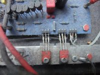
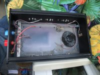
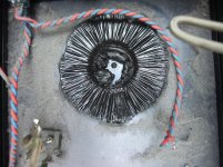
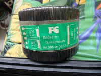
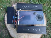
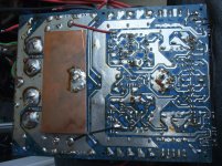
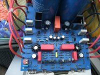
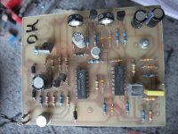
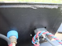
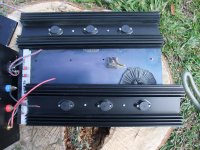
The power mono amps arrived. Some pictures:
Attachments
-
 DSCF1863.jpg998.7 KB · Views: 980
 -
 DSCF1864.jpg991.7 KB · Views: 950
 -
 DSCF1865.jpg952.4 KB · Views: 875
 -
 DSCF1867.jpg1,001.5 KB · Views: 857
 -
 DSCF1873.jpg926.7 KB · Views: 370
 -
 DSCF1876.jpg1,021.7 KB · Views: 326
 -
 DSCF1877.jpg988.4 KB · Views: 358
 -
 DSCF1882.jpg990.2 KB · Views: 343
 -
 DSCF1885.jpg912.2 KB · Views: 303
 -
 DSCF1892.jpg988.8 KB · Views: 297
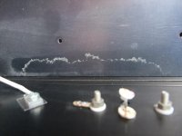
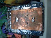
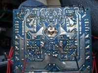
more pictures PCB solder side
Attachments
Who know, how many different versions are on the marked?
Unterschied Omtec CA 60 V2 und V3, Verstärker/Receiver - HIFI-FORUM
CA-25 und CA-60 Class-A-Monoblöcke
Baujahre 1985 bis 1998 (V1)
Baujahre 1985 bis 1998 (V1)
Omtec CA-25 V2 Class A Endstufen
Die Geräte stammen wohl aus 2003.
no class switch...
Would like to learn what tells v2 from v2...
Would like to learn what tells v2 from v2...
Pricelist Omtec (Januar 2005):
CA-25 V3 2005
Review: Omtec CA-25 V3 Amplifier25W for 8 0hm , 50 for 4ohms, Version3, Gain 22dB, Input Impedance>100kohms, speed rate 0,46 µs, Input RCA and XLR,
2 switches in front (one for on/off – the other one for Class A or AB)
2 switches in front (one for on/off – the other one for Class A or AB)
hth
Ulli
PS:
I own CA-25s, too.
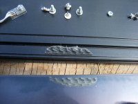
New caps might be a good idea - just in case you'ld like to share some info...
A while ago I had to re-solder the cap screws...

Last edited:
good informations - thank you very much.
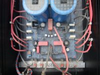
If I look to your picture, I guess, there is a special soldering tin for soldering the aluminum terminals of capacitors in use.
Therefore the follow question rises up:
What is the best way to solder aluminum together with copper ?
in this case also this thread is of interest:
http://www.diyaudio.com/forums/solid-state/137753-outsider-mono-power-amplifiers.html
Last edited:
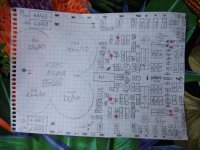
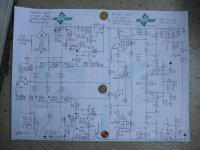
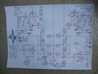
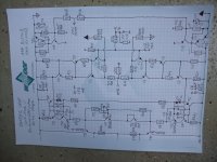
Omtec Mono Power Amplifier "CA 25" (CA25) - Schematic Diagram
Please note: In the schematic from the images are probably still many errors.
About error hints, I am happy of course.
Information on current flows and voltage values will follow soon.
Yes, I think so, too. But this isn't a good solution due to excessive heating of the internal connection of the caps. Caps with srew terminals instead solder terminals are not make for solder.It appears from the pic, that the soldering is to steel capacitor mounting screws - after tightening. Are they really aluminium screws? I doubt that any soldering to aluminium would be used, as it is usually quite difficult and likely would void the capacitor warranty.
Please note: In the schematic from the images are probably still many errors.
About error hints, I am happy of course.
Information on current flows and voltage values will follow soon.
Attachments
Last edited:
Both mono amp devices are now in working condition. Idle current at the darlington output stage on both devices is 1250mA and very stable, i. e. both immediately after switching on and after the warm-up phase nearly the same value.
But one observation confuses me:
from the in parallel mode working darlingtons are great differences:
the lowest value is 195mV and the highest value 334mV (voltage measured at the 0,68 ohm emitter resistors)
This is due the Ube voltage tolerances - so I think. Am I right?
Which influence does have this to the sonic quality?
Next time I will upload the updated schematics.
Last edited:
yes, the values are little different (between 676 and 683 mR). But to little for the observated variation at idle current.Normally one would expect equal current through those resistors.
Sound quality will most likely be degraded in case of different currents.
Have you checked the 0r68 resistors for having the same value?
While upload the updated schematics I get this message:
413 Request Entity Too Large
what is the reason ?
Hi Andreas,
I took a look a the schematics. It provides regulated voltage for VAS and input. And has a servo that ensures correct offset.
The VAS is cascoded, but the cascode voltage is modulated.
But I do not understand the input stage. Could you explain it please? I would like to understand.
I took a look a the schematics. It provides regulated voltage for VAS and input. And has a servo that ensures correct offset.
The VAS is cascoded, but the cascode voltage is modulated.
But I do not understand the input stage. Could you explain it please? I would like to understand.
Hi,
I try to understand and explain. Please correct me. I'm NO EXPERT. I just want to learn.
My idea of how it could work:
"T5 and R1 form a constant current source.
T1 is a emitter follower working on the constant current source.
Therefore, base of T7 is on fixed voltage.
T3 together with T7 is a cascoded input amp. The feedback is current feedback on the emitter of T3.
The DC balance is done by shifting DC of the emitter."
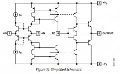
The Input stage is a heavily cascoded symmetrically realized buffered current feedback input stage, which couples into a high linearity push pull current mirror ("VAS").
If you take a look into classic CFB-OPAs like AD844 or AD846 you'll see very similar circuitry.
The basic topology is the one of a transimpedance stage (input + mirror) and a power buffer.
If you take a look into classic CFB-OPAs like AD844 or AD846 you'll see very similar circuitry.
The basic topology is the one of a transimpedance stage (input + mirror) and a power buffer.
Attachments
- Home
- Amplifiers
- Solid State
- Omtec Mono Power Amplifier "CA 25" (CA25) - Schematic wanted