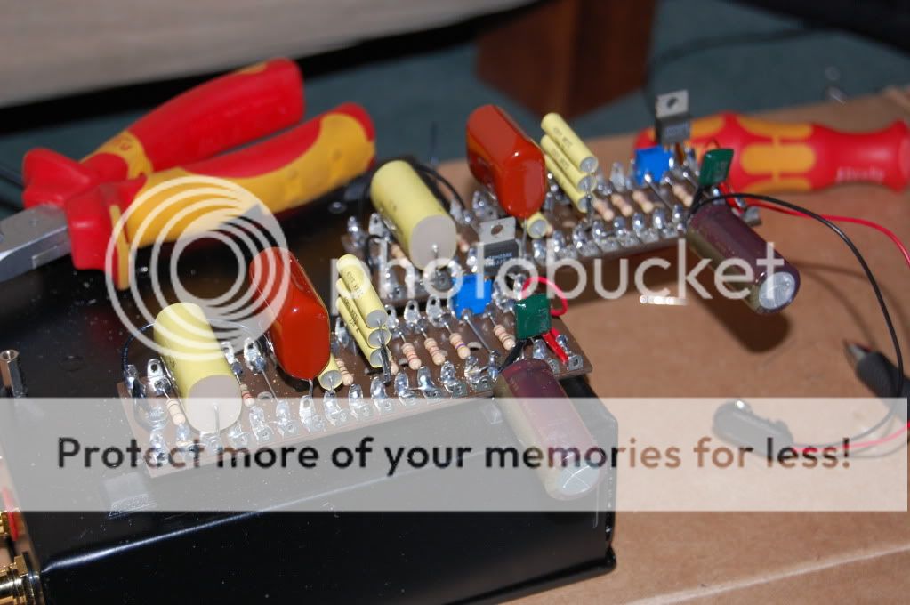
You may have seen my earlier posts, I just built this Battery Pacific phono stage, based on the circuit in this diyaudio thread,
http://www.diyaudio.com/forums/showt...0&pagenumber=1:

I pretty much stuck to this circuit apart from some minor resistor value differences and the coupling cap before the second stage is a 560nf but I dont think that would cause this problem.
I have previously built essentially the same circuit with bog-standard film caps and wirewound resistors and was so impressed I wanted to build it again with decent PP caps and carbon resistors and this time Battery power.
When it is connected to a stylus there is a low level whitish noise like a badly tuned radio and when there is no stylus connected it acts like a microphone, if you tap on the metal case you hear a sound like a metal case been tapped if you cratch the metal caseyou hear a sound like a metal case been scratched. When you play a record it sounds great, but the white noise is still present.
I'm not great with the theory but I always get a great response here; Anyone got any idea what's going on?
http://www.diyaudio.com/forums/showt...0&pagenumber=1:
I pretty much stuck to this circuit apart from some minor resistor value differences and the coupling cap before the second stage is a 560nf but I dont think that would cause this problem.
I have previously built essentially the same circuit with bog-standard film caps and wirewound resistors and was so impressed I wanted to build it again with decent PP caps and carbon resistors and this time Battery power.
When it is connected to a stylus there is a low level whitish noise like a badly tuned radio and when there is no stylus connected it acts like a microphone, if you tap on the metal case you hear a sound like a metal case been tapped if you cratch the metal caseyou hear a sound like a metal case been scratched. When you play a record it sounds great, but the white noise is still present.
I'm not great with the theory but I always get a great response here; Anyone got any idea what's going on?
this is typical, because there are low currents and high impedances. By MM RIAA head amps with tubes the same effects are to observe.
You can reduce the microfonic effects by the use of a very heavy board for putting up your RIAA device (at best sandwich structure, inside a mixture of lead shut and sand for birdcages).
How much is the noise? More or few as that one from the neutral groove from your record disc?
Noise like a badly tuned radio indicates oscillation (an introduce of an gate stopper resistor of 1-5 K-Ohm near at the Gate of the input jFET can help)
If by tap on the metal case I hear a sound like a metal case, it is necessary, to coated your plates with bitumix or similare suited damper stuff (the ventilation and thermal management shall not be influenced !!)
For the ultimate sonic quality microphonic must be greatly reduced.
Therefore, a certain sound quality level isn't break with tube technology. And therefore tube technology by RIAA head amps is only recommend by low and medium cost devices and not for top class products.
Last edited:
this is typical, because there are low currents and high impedances. By MM RIAA head amps with tubes the same effects are to observe.
You can reduce the microfonic effects by the use of a very heavy board for putting up your RIAA device (at best sandwich structure, inside a mixture of lead shut and sand for birdcages).
How much is the noise? More or few as that one from the neutral groove from your record disc?
Noise like a badly tuned radio indicates oscillation (an introduce of an gate stopper resistor of 1-5 K-Ohm near at the Gate of the input jFET can help)
If by tap on the metal case I hear a sound like a metal case, it is necessary, to coated your plates with bitumix or similare suited damper stuff (the ventilation and thermal management shall not be influenced !!)
For the ultimate sonic quality microphonic must be greatly reduced.
Therefore, a certain sound quality level isn't break with tube technology. And therefore tube technology by RIAA head amps is only recommend by low and medium cost devices and not for top class products.
Where the drain resistors specify 2k4 I have used 2k7 and the FETs are matched at about 6.4-6.5 mA, could reducing these drain resistors help?
I very much doubt it. As tief says, with such high impedance the leakage capacitance from the oc input to the case is sufficient to create a signal. As the case vibrates, the small change in distance changes the capacitance value, the charge is constant so there must be a voltage change. Gain it up 60dB and hey presto - you just made a microphone.
If you calculate the effective thermal noise generated by a resistor equivalent to your cartridge, does it jive with what you're seeing for noise?
If you calculate the effective thermal noise generated by a resistor equivalent to your cartridge, does it jive with what you're seeing for noise?
Funny thing, now I've had it running for a couple of hours the noise has stopped, I turned it off for half an hour, turned it back on, the noise came back and then faded out after a few seconds and seems to be running silent now; Well I'm confused, I'll keep an eye on it for a while.
I forget to mention a second thing: the circuit from post #1 is castrated "Pearl" RIAA head amp - basicly the same topology, namely a passive RIAA network between two line stages with voltage gain.
http://www.passdiy.com/pdf/pearlphono.pdf
For me in general the royal way to get ultimate audible sonic quality.
The reason for very fine results by the "PEARL" phono stage is not the use of cascode topology, but the paralleling connected jFET devices, especially for the input. So you get more idle current and lower noise.
Because of the higher current flow at whole the RIAA network can have lower impedance (i. e. lower resistor values and higher capacities)
The first step for you must be to check out, if there are oscillation or not by the follow three modes:
1) input shortet
2) input open (only the presently input resistance)
3) cartridge coil as input load (normal mode)
In none of these modes oscillation may occur, otherwise there are errors regarded the leading (Cable Management) and layout - unfortunately mostly hard to find. If I see the kind of build, my assumption is quite likely.
If you use for drain resistor 2k4 instead 2k7, you will not have appreciable effects.
But I missed the neg. voltage for exactly gate bias adjusting the middle point of voltage
Last edited:
Cheers Tief, but what do you mean here?But I missed the neg. voltage for exactly gate bias adjusting the middle point of voltage
I mean the adjust for symmetric clipping respectively for adjust the lowest distortion if the voltage swing is in the aera below 1VssCheers Tief, but what do you mean here?
The great advantage now is the possibility to use many different jFETs independend of their individual gate-source threshold voltage values.
By use of paralleling connected jFET devices each jFET get it's own adjust. Now you must only select of identical transfer curvatures - individual threshold voltage values are now no matter.
By the way - a useful update for new "PEARL" projects.
Attachments
Last edited:
Since you already built one version of this preamp, and it didn't suffer from the noise effects that you describe here, then I would look at the differences first.
You have two issues; noise and microphonics. They may have a common cause, maybe not.
I assume the noise and microphonics are the same for both channels?
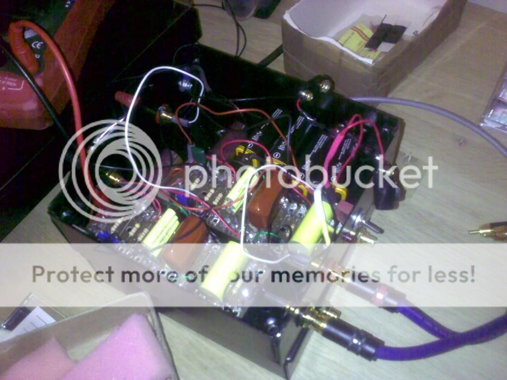
Some of the noise could be in your power supply. Looks like you've bypassed them, the regulators too? Batteries can produce some noise, and this is a high gain device.
Some caps can be microphonic, if they are not wound tightly or leads are not firmly attached. Those caps don't look suspect, and I would put this issue low on the list.
Poor solder joint can lead to noise and microphonics. This could be an issue if the noise is localized to one channel especially.
Different layout could lead to oscillation or more microphonics than the first version.
Are any connections longer than your first version, especially to the FET gates or drains. As Tief. mentioned, try a stopper resistor.
Is the metal case earthed?
The microphonics could be just a mechanical issue. Tap gently with a non conductive probe and see where the effect is loudest. Look at your component and joints there. You may be able to isolate that issue.
Sheldon
You have two issues; noise and microphonics. They may have a common cause, maybe not.
I assume the noise and microphonics are the same for both channels?
Some of the noise could be in your power supply. Looks like you've bypassed them, the regulators too? Batteries can produce some noise, and this is a high gain device.
Some caps can be microphonic, if they are not wound tightly or leads are not firmly attached. Those caps don't look suspect, and I would put this issue low on the list.
Poor solder joint can lead to noise and microphonics. This could be an issue if the noise is localized to one channel especially.
Different layout could lead to oscillation or more microphonics than the first version.
Are any connections longer than your first version, especially to the FET gates or drains. As Tief. mentioned, try a stopper resistor.
Is the metal case earthed?
The microphonics could be just a mechanical issue. Tap gently with a non conductive probe and see where the effect is loudest. Look at your component and joints there. You may be able to isolate that issue.
Sheldon
Last edited:
If you use for drain resistor 2k4 instead 2k7, you will not have appreciable effects.
No effect in the second position, but a small effect on the RIAA curve for the input drain resistor. In either case, no influence on noise or microphonics.
Sheldon
BTW carbon comp resistors will be noisier and less stable than wirewounds. Wirewounds are the least noisy, carbon comp. the most.
Last edited:
If you use for drain resistor 2k4 instead 2k7, you will not have appreciable effects.
No effect in the second position, but a small effect on the RIAA curve for the input drain resistor.
Sheldon
I think I've tracked it down to the long connections between the connectors and the Gate of the first FET, I left them quite long so I could adjust stuff out of the case, I'll replace them with shorter screened cables and try some stopper resistors if that doesnt do it.
THe circuit is pretty much the same as the previous attempt, but the construction is completly different, the old preamp was built in a very small space on strip-board, the newone uses huge components on tag board.
THe circuit is pretty much the same as the previous attempt, but the construction is completly different, the old preamp was built in a very small space on strip-board, the newone uses huge components on tag board.
The length of the lead in shouldn't be too much of a problem. It's possible that it could pick up some RF noise, if you are in a noisy environment. Make sure the lead to the gate from the 47k input resistor is short. Same for the drain resistor. If you use a stopper, put it right next to the gate.
Sheldon
Sheldon
- Status
- This old topic is closed. If you want to reopen this topic, contact a moderator using the "Report Post" button.
- Home
- Amplifiers
- Solid State
- Wierd Interference on Phone Pre