hello
i have to say, i have no idea how to design a transistor based amplifier.
absolutely not, if anyone knows good books/websites for that, please say so.
well, after that, i sort of designed a high power opamp.
i found a discrete opamp design on the internet somewhere and build it, it actually worked quite well, considering i made it on perfboard and didnt match anything.
but well, the power of it was low, really low.
so i was wondering, if i put some BD139/BD140's after it, do i get more power.
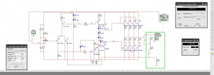
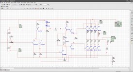
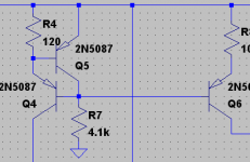
after some multisim adventures i came up with something, schematic should be attached.
the resistors in the green square are the load resistor, 8 ohm, and the 2 resistors for the amplification factor, 5K and 500ohm, giving 10 times amplification.
the opamp is used as a non inverting amp.
its a discrete opamp, and some BD139/BD140 behind it as darlington for more power.
in multisim i get around 15 watts with a 8 ohm resistor as load before the distortion goes up.
the distortion meter gives a nice 0.001% in 1 watt, after all it all seems working.
i am making a PCB at the moment in eagle, when its done i will post it to.
but will it work in real life to, with a decent quality?
i dont except something amazing, but i hope for something decent.
and whats a nice amplification factor for this?
my CD player/PC give a 2Vpp signal.
thanks in advance
rik
i have to say, i have no idea how to design a transistor based amplifier.
absolutely not, if anyone knows good books/websites for that, please say so.
well, after that, i sort of designed a high power opamp.
i found a discrete opamp design on the internet somewhere and build it, it actually worked quite well, considering i made it on perfboard and didnt match anything.
but well, the power of it was low, really low.
so i was wondering, if i put some BD139/BD140's after it, do i get more power.
after some multisim adventures i came up with something, schematic should be attached.
the resistors in the green square are the load resistor, 8 ohm, and the 2 resistors for the amplification factor, 5K and 500ohm, giving 10 times amplification.
the opamp is used as a non inverting amp.
its a discrete opamp, and some BD139/BD140 behind it as darlington for more power.
in multisim i get around 15 watts with a 8 ohm resistor as load before the distortion goes up.
the distortion meter gives a nice 0.001% in 1 watt, after all it all seems working.
i am making a PCB at the moment in eagle, when its done i will post it to.
but will it work in real life to, with a decent quality?
i dont except something amazing, but i hope for something decent.
and whats a nice amplification factor for this?
my CD player/PC give a 2Vpp signal.
thanks in advance
rik
Attachments
hello
i have to say, i have no idea how to design a transistor based amplifier.
absolutely not, if anyone knows good books/websites for that, please say so.
well, after that, i sort of designed a high power opamp.
i found a discrete opamp design on the internet somewhere and build it, it actually worked quite well, considering i made it on perfboard and didnt match anything.
but well, the power of it was low, really low.
so i was wondering, if i put some BD139/BD140's after it, do i get more power.
after some multisim adventures i came up with something, schematic should be attached.
the resistors in the green square are the load resistor, 8 ohm, and the 2 resistors for the amplification factor, 5K and 500ohm, giving 10 times amplification.
the opamp is used as a non inverting amp.
its a discrete opamp, and some BD139/BD140 behind it as darlington for more power.
in multisim i get around 15 watts with a 8 ohm resistor as load before the distortion goes up.
the distortion meter gives a nice 0.001% in 1 watt, after all it all seems working.
i am making a PCB at the moment in eagle, when its done i will post it to.
but will it work in real life to, with a decent quality?
i dont except something amazing, but i hope for something decent.
and whats a nice amplification factor for this?
my CD player/PC give a 2Vpp signal.
thanks in advance
rik
That schematic will not work until you get some power to R4 and D1. There are much better choices for output transistors as those are only 1.5A continuous. Paralleling helps but at your power level you should not need multiple devices. Why the need for Q4 when you're only running 7mA ? You'd likely get better results by using more current into Q2 and Q3. You might want to add a large capacitor between R16 and ground to reduce the gain to unity at DC. Just my $0.02
G²
thank you for your 2 cent, but its just 1,5 cent in europe 
as i said before, i have absolutely no idea what i did, no formulas, nothing.
i foudn the schematic of the discrete opamp i used, its here:
CLICK ME
i combined it with this, sort of, for more power:
OW MY
and well, i posted the result in the start post.
i removed Q4, and distortion is still the same.
a 100uF cap between R16 and ground, and distortion still 0.001%
and then i was thinking, more power trough Q2/Q3 and R4/D1
how do i do that, so i lowered the resistance of R4 and R6.
when measuring with a 4 ohm load i measured 0.003% before the chances and 0.001% after, so it seems like it improved.
so less parts, and less distortion, sounds nice to me haha
and i assume this amp is running in class A/B, if i remove the transistors i got cross over distortion, meaning its class B, so with my little bit of amplification knowledge i came up with that
rik
as i said before, i have absolutely no idea what i did, no formulas, nothing.
i foudn the schematic of the discrete opamp i used, its here:
CLICK ME

i combined it with this, sort of, for more power:
OW MY
and well, i posted the result in the start post.
i removed Q4, and distortion is still the same.
a 100uF cap between R16 and ground, and distortion still 0.001%
and then i was thinking, more power trough Q2/Q3 and R4/D1
how do i do that, so i lowered the resistance of R4 and R6.
when measuring with a 4 ohm load i measured 0.003% before the chances and 0.001% after, so it seems like it improved.
so less parts, and less distortion, sounds nice to me haha
and i assume this amp is running in class A/B, if i remove the transistors i got cross over distortion, meaning its class B, so with my little bit of amplification knowledge i came up with that
rik
Attachments
Removing R7 should decrease distortion, especially at HF.
In class B there will be a fast rise in distortion at higher frequencies. Try simulating at 1k and 20k and see what happens. I would recommend replacing the diodes with a Vbe multiplier so you can set the bias current at just the right level.
Also put a 22u cap between the bases of Q6 and Q7. The driving current for Q6's base has to go through these diodes, and this will cause the bias current for the outputs to modulate.
Distortion in real life will tend to be larger depending on layout (or even lower depending on models). You've got the basic circuit and if built correctly it should sound good, but there are some minor improvements that can be made.
What do you plan on using this amp for?
- keantoken
@ 20Khz i get 0.018& distortion, when i removed R7 it went to 0.014%
i'm going to look up some information about the Vbe multiplier, never heard of it to be honest.
websites and books with more information how to design amplifiers is always appreciated
its going to be used for testing purposes only, so not in a real life situation.
if it works well, i might make a small PC amplifier with it
Last edited:
To make it simple:
Voltage source - Wikipedia, the free encyclopedia
Scroll down to the Vbe multiplier section. Look at R2. Say this resistor is 680 ohms. If 1mA flows through this resistor, the transistor will begin to turn on. By this time 1mA is also flowing through R1. So if we assume R1 and R2 are 680 ohms each, then we get .68V*2, which comes to 1.36V.
If we double R2 to about 1.2k, we add another Vbe to this, giving somewhere around 1.8V. The transistor won't let the current through R2 get above 1mA, because it then turns on and decreases Vout.
So you could say a Vbe multiplier is like a zener diode, except you can change the output voltage.
To fit it in your current circuit, replace R1 with a 5k trimmer resistor. Then you can adjust the bias current of the circuit to be class A, AB, or B depending on your requirements.
- keantoken
Last edited:
You can turn a 2n2222 Base-Emitter junction backwards,
and abuse as a Zenier. Of course, its supposedly useless
for gain afterward, but that would be real low part count
"transistor" voltage reference.
I'm not sure bout tempco... I thought all Zeniers gravitate
toward 6.3V as they get hot? I suspect reverse breakdown
of VEB is less than 6.3V, so VEB tempco might be positive?
If so? One more reason to ignore this post and move along...
Sorry to distract.
Actually, Wikipidea sais the magic voltage is 5.6, and the
tempco always gravitates away from 5.6, not toward it...
So maybe VEB or any other low-tech Zenier below 5.6V
might still stand a chance of being useful here?
Last edited:
I would suggest removing R13 and increasing C1 to 100pF for now. After tweaking the design we can worry about stability. This will increase HF THD temporarily.
Firstly, bias is important. How much current do you want your amp to draw? The higher the bias, generally, the lower the distortion. I'm guessing you want to avoid class B bias, where there is no crossover region between the devices. Then we have class AB and class A. IT is recommended not to go between these. In class AB, the best compromise bias level is obtained for lowest distortion and highest efficiency. In class A, neither device ever turns off and it is considered wasteful - but distortion is very, very low. (I would recommend class AB for a discrete opamp, and maybe a class A switch for "low THD" mode)
To adjust for class AB, place a probe between Q4's base and the output, and adjust R2 so that the sine wave displayed shows no jerks or odd places (or you could simply adjust with a THD meter between these two points, though I don't think it's necessary)
So:
1: I would reccommend a 22uF cap placed across the Vbe multiplier, to make the bias stable at audio frequencies (this is common practice, but it may not have much of an affect here)
2: A 100 ohm resistor between the emitters of Q6 and Q7. These transistors should not turn off, and this resistor will help ensure that. If they do turn off, it will result in transients and HF garbage.
3: R5 should be twice the value of R4, so that the Ic of Q2 and Q3 are the same. This will lower distortion, as the Vbe's of these transistors will cancel better.
As for reading material, Doug Self's site has lots of good stuff on there. Reading through this section on discrete design taught me a lot:
Distortion In Power Amplifiers
- keantoken
hmm, for the bias, when the potentiometer is at 50% i get around 0.6% distortion, at 60% its down to 0.01% and anything above 70% the distortion is at 0.005%
what would be a good value then?
adding a 22uF C didn't improve anything in the simulation, but didn't make anything worse.
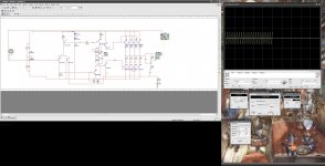
the 100ohm resistor between Q6 and Q7 made multisim go berserk.
at a high frequency distortion went above 4%
got a scope screenhot of it in the attachments.
what would be a good value then?
adding a 22uF C didn't improve anything in the simulation, but didn't make anything worse.
the 100ohm resistor between Q6 and Q7 made multisim go berserk.
at a high frequency distortion went above 4%
got a scope screenhot of it in the attachments.
Attachments
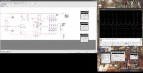
That's not distortion. It's HF instability and oscillation.the 100ohm resistor between Q6 and Q7 made multisim go berserk.
at a high frequency distortion went above 4%
The 100R resistor is a good idea though. I'd recommend putting that back and then fixing the HF instability by removing R13 and increasing C1.
Best bias for class AB is if you adjust it so that (with no input signal) there's about 25mV DC across each of the output stage emitter resistors (R11, R12 and R17 to R22).
To keep the bias stable with a real amp, Q4 needs to be stuck on the same heatsink as the output transistors. If they're all separate, sticking Q4 on one of them should be good enough. Doing the same for Q6 and Q7 would help too. The idea is that Q4 must compensate for the Vbe change versus temperature of the other transistors, so it helps if they're all the same temperature when things start heating up.
Something else worth trying is putting equal value resistors in series with the emitters of Q2 and Q3. Try something like 470 ohms each. That will improve HF stability without hurting the slew rate and will also improve the input-stage linearity.
This is very common in discrete amplifiers, but not often seen in opamp schematics because fabricating resistors on the silicon is a pain.
btw, You could end up with a very nice amp here. I've sometimes thought of using multiple BD139/BD140 as output devices.
e.g. using ten of them in parallel gives about the same useful power dissipation as a 2N3055, with none of the secondary breakdown limits and about 100 times the speed - actually even faster than any of the more modern output devices I've seen.
Heatsinking is easy too, if you start with rectangles of sheet metal (copper or aluminum), say 3 inches square with a hole about 1/2 inch from one side, and make a sandwich, alternating transistors and metal plate, with one long bolt through the whole lot to hold it together.
Cheers - Godfrey
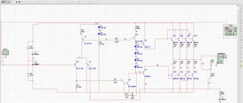
i made those chances, making C1 100pF helped a lot.
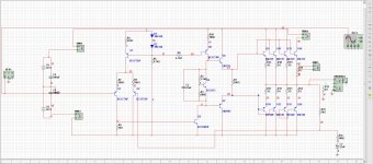
with a 2.3K ohm resistor in the Vbe multiplier the voltage over the output stage emitter resistors is 22.8mV, good enough.
i added 2 470 ohm resistors in the emitters of Q2/Q3, and the amp died, changed R4 to 220ohm and everything was back and running again.
distortion is very low now, 0.002% @10Khz 1 watt, 0.011% @50Khz 1 watt.
funfunfun, i get 0.6% distortion @ 1Mhz 0.15 watt, absolutely not useful, but kinda funny.
and i got some nice heatsinks, and thermal 2 component glue, should work fine
current schematic is in the attachment
Attachments
Last edited:
Nice.
But now make a frequency response graph going up to 500MHz. Look for spikes in the gain at HF. Also, try putting a 100nF cap across the load. As an opamp, it should be stable into capacitive loads. (speaker cables always have some capacitance, not to mention opamps are used for more than just audio)
I'm fairly sure you'll find C1 is necessary.
- keantoken
hehe had a busy weekend, but tested some more stuff.
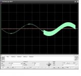
without C1 i indeed get a big spike around 30Khz, making C1 10pf fixes it.
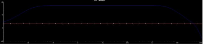
the only problem i see is that very low tones are amplified less, i added a graph from multisim to show it.
and well, everything above 10Hzt is important imho
and for the CCS arrangement, this is for Q1?
without C1 i indeed get a big spike around 30Khz, making C1 10pf fixes it.
the only problem i see is that very low tones are amplified less, i added a graph from multisim to show it.
and well, everything above 10Hzt is important imho
and for the CCS arrangement, this is for Q1?
Attachments
Yes, I'm speaking about Q1.
riktw, Nigel has a good idea. search "discrete opamp" on google and you'll find what you're looking for. The below is very interesting, particularly the section on ceramic capacitors...
http://www.johnhardyco.com/pdf/990-2007.pdf
Nelson Pass. Although this isn't the super-low distortion approach.
http://www.passdiy.com/pdf/diyopamp.pdf
Forssell Technologies
4QD-TEC: discrete op-amps
- keantoken
- Status
- This old topic is closed. If you want to reopen this topic, contact a moderator using the "Report Post" button.
- Home
- Amplifiers
- Solid State
- diy discrete high power opamp