... a MONSTER of an amplifier ")
...fuelled by drinking too much Scotch.
Either the final version will explode in my face, leaving me with permanent scars, full removal of all facial hair...or it'll provide the quality and current I need to run ribbon speakers properly.
So development has started in minature scale first.
...fuelled by drinking too much Scotch.
Either the final version will explode in my face, leaving me with permanent scars, full removal of all facial hair...or it'll provide the quality and current I need to run ribbon speakers properly.
So development has started in minature scale first.
Attachments

Last edited:
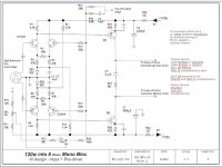
Based on thinking behind an earlier Levinson design I saw back in the late 1990's I'm mucking about with a symmetrical current mirror input stage - get slew rate up - noise down and aiming for low distortion with devices available on the market today. Last time I designed an amp was 1996 - technology has moved on since then, I'm pleased to say.
Attachments
Member
Joined 2009
Paid Member
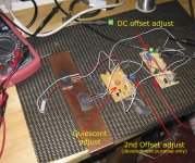
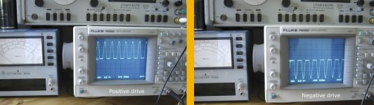
I was working on this until 3.00am - dogged by a couple of problems
Managed to get positive and neg drive near perfect
but have xover distortion at 160Khz when testing extreme HF performance
Not quite got the gain I was hoping for yet.
What I may do is swap BC550 and 560s for the 2SC2240 and 2SA970 pairs for the input
Managed to get positive and neg drive near perfect
but have xover distortion at 160Khz when testing extreme HF performance
Not quite got the gain I was hoping for yet.
What I may do is swap BC550 and 560s for the 2SC2240 and 2SA970 pairs for the input
Attachments
Last edited:
Banned
Joined 2002
Banned
Joined 2002
Hi jleaman
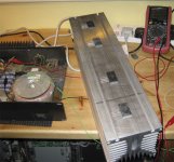
A heatsink designer/manufacturer near me they sorted me the copper bars also
I have some more on the way for the 120W version of this -- the big monster sinks are for the 300Watt variant I'll build if I get the 120Watt correctly adjusted.
Very sexy heat sink's, would be good for a nice Class A Beast!
instability made me change design
Been having some instability issues - so been a while since posting - not getting the neg feedback chain and zobel filter problems totally ironed out, it's put a bit of delay into the project -- it's also made me change the bias chain to look at current shunt. - I've taken out the pre driver stage as it was offering nothing more than overcomplicating the design. I'm now looking over the zobel trap
Design beginning to come together - through some trial and error - the control relating to forward feed into the rear of the two current mirrors has been causing some induction of RF oscillation and I'm not entirely sure why yet.
My initial trials have made me change post bias drivers - but has set me to use the BC550c and BC560c for the current mirror front end. Managed to get down to...
...spectral density of 3.9 nV/√Hz using my Racal spectrum analyser
with input offset current only 2.7nV -
but this was working in miniature at ±20V - not yet the full ±55V the finished design will be loaded with.
as for the rest of the circuit -- I've yet to devlop it fully
with the issues I am having with feedback loops - I managed to turn it into a 2Mhz oscillator -- not very funny because I'm not trying to make a radio transmitter.
Attachments
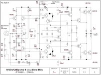
Are you sure that circuit diagram is correct?
You can't parallel output transistors like that in a CFP output stage, i'd suggest you add a second driver so each output transistor has it's own driver with emitter resistor to the output. As you have it there (well on that circuit diagram at least) you'll get unequal current sharing as there is no emitter resistor between (output transistor) emitter & supply rail. If you add a second driver & totally seperate the outputs the emitter resistor to the output will keep things in order. In which case you only need to match driver VBE Don't forget that with a CFP output the bias transistor needs to be tracking the drivers thermally
That's not the half of what i can see that looks a bit messy, sorry but memory of that circuit isn'ty good after a few

E2A:- Just noticed it's got an output triple. I stand by what i say though, add a second driver & thermally track them along with the other drivers, the pre-drivers shouldn't get that warm at all & the drivers are where you'll get best thermal stability with the bias transistor.
You can't parallel output transistors like that in a CFP output stage, i'd suggest you add a second driver so each output transistor has it's own driver with emitter resistor to the output. As you have it there (well on that circuit diagram at least) you'll get unequal current sharing as there is no emitter resistor between (output transistor) emitter & supply rail. If you add a second driver & totally seperate the outputs the emitter resistor to the output will keep things in order. In which case you only need to match driver VBE
Don't forget that with a CFP output the bias transistor needs to be tracking the drivers thermally That's not the half of what i can see that looks a bit messy, sorry but memory of that circuit isn'ty good after a few
E2A:- Just noticed it's got an output triple. I stand by what i say though, add a second driver & thermally track them along with the other drivers, the pre-drivers shouldn't get that warm at all & the drivers are where you'll get best thermal stability with the bias transistor.
Last edited:
Comp feed bipolar pairing
Hey event
thanks very much for taking an interest. The back end is messy at the moment - I really havent thought that far ahead yet - managed to get the mirrors working and I'm pretty impressed with the input performance and output gain from them, though I elected to change bais stage. this change has knock on effects. So I am rebuilding the bench prototype to see what adjustments and compromises I can make.
I'll take your approach on thermal tracking - gauging where to locate everything on these heatsinks for maximum efficiency is going to take some thinking about.
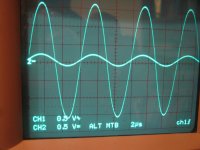
I invite you to take a look at my first four posts - to see where I started from - the scope shows the really clean performance of the current mirrors in an extreme HF test. As you see - no droop or triangulation of any kind at 160Khz... just a tiny shift in phase compared to input - However, in the audio register, that phase shift doesnt manifest. I'm attempting to carry that sort of clean performance forward into the other stages- attacking noise and distortion at every stage, whilst trying to find the best materials and techniques.
cheers
PLL
.
Hey event
thanks very much for taking an interest. The back end is messy at the moment - I really havent thought that far ahead yet - managed to get the mirrors working and I'm pretty impressed with the input performance and output gain from them, though I elected to change bais stage. this change has knock on effects. So I am rebuilding the bench prototype to see what adjustments and compromises I can make.
I'll take your approach on thermal tracking - gauging where to locate everything on these heatsinks for maximum efficiency is going to take some thinking about.
I invite you to take a look at my first four posts - to see where I started from - the scope shows the really clean performance of the current mirrors in an extreme HF test. As you see - no droop or triangulation of any kind at 160Khz... just a tiny shift in phase compared to input - However, in the audio register, that phase shift doesnt manifest. I'm attempting to carry that sort of clean performance forward into the other stages- attacking noise and distortion at every stage, whilst trying to find the best materials and techniques.
cheers
PLL
.
Last edited:
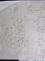
Hi loopy, i hope you don't mind me calling you that Every time i see your online name & your avatar it puts a smile on my face
I thought i'd put a little bit more meat on the bones of what i posted yesterday, you may well understand what i was jibbering about but maybe not so i scrawled a couple of diagrams for you. Hope you don't mind.
First up the way to get what you have working & the output transistors sharing properly. To do this you are going to need to match the VBE of the output transistors & i'd suggest that seeing as you want to go class A that you do it full quiescent current.

That'll make it work. You may notice the dotted lines pointing towards some low value resistors, you might need to install these for stability. I'd suggest that somewhere in the low ohmic region would be ok, possibly 10 ohms or less. Trial & error will tell no doubt but the lower the better to increase efficiency.
The following is what i was trying to get accross in my last post...

In this case you notice the dual drivers. Pre drivers are singular as before. Doing things this way you don't need to match the output transistors, instead you need to match the two drivers that are on each side You'll notice that there are now no emitter transistors on the emitters of the output transistors & this will increase the amplifiers efficiency.
In both circuits you want the drivers (be it two or 4) mounted on a seperate heatsink to the output transistors & the bias compensation transistor mounted on the same smaller heatsink as the drivers. It doesn't matter how much heat the output transistors have to deal with (within reason obviously), it's the drivers that need to be monitored to keep the quiescent current stable as they have the base/emitter junction connected to the output. The output transistors are in a feedback loop controlled by the drivers so can be ignored
E2A:- You may need to install some small resistors in the second circuit like i pointed out in the first circuit (for stability), again look at low ohmic values...
Good luck & have fun!
Every time i see your online name & your avatar it puts a smile on my face I thought i'd put a little bit more meat on the bones of what i posted yesterday, you may well understand what i was jibbering about but maybe not so i scrawled a couple of diagrams for you. Hope you don't mind.
First up the way to get what you have working & the output transistors sharing properly. To do this you are going to need to match the VBE of the output transistors & i'd suggest that seeing as you want to go class A that you do it full quiescent current.
That'll make it work. You may notice the dotted lines pointing towards some low value resistors, you might need to install these for stability. I'd suggest that somewhere in the low ohmic region would be ok, possibly 10 ohms or less. Trial & error will tell no doubt but the lower the better to increase efficiency.
The following is what i was trying to get accross in my last post...
In this case you notice the dual drivers. Pre drivers are singular as before. Doing things this way you don't need to match the output transistors, instead you need to match the two drivers that are on each side
You'll notice that there are now no emitter transistors on the emitters of the output transistors & this will increase the amplifiers efficiency.In both circuits you want the drivers (be it two or 4) mounted on a seperate heatsink to the output transistors & the bias compensation transistor mounted on the same smaller heatsink as the drivers. It doesn't matter how much heat the output transistors have to deal with (within reason obviously), it's the drivers that need to be monitored to keep the quiescent current stable as they have the base/emitter junction connected to the output. The output transistors are in a feedback loop controlled by the drivers so can be ignored
E2A:- You may need to install some small resistors in the second circuit like i pointed out in the first circuit (for stability), again look at low ohmic values...
Good luck & have fun!
Comp feedback bipolar pair
Hi Event
hehehe - No worries on the name -- it's because I dont take myself too seriously
Yeah - quite right in your post - spot on -- the 2nd image is the one I'll stick with -- I'll adopt that approach, thanks for that.
I managed to get the input stage working and I'm really happy with its performance. Now I want to carry this good performance right through the rest of the design - attacking noise and distortion.
The final intended load for this Amplifier is a pair of ribbon speakers
I'll recreate the bench model to your output stage
I am making a new bench development mule - I've decided to change the MPSW42-92 idea into MJE172 MJE182 comps before the final 2SA1216 and 2SC2922s - so all are part of the themal management - getting benefit of thermal stability by mounting them in appropriate proximity on the heatsinks.
I dont have the benefit of simulator software -- does anyone know what's best???
Hi loopy, i hope you don't mind me calling you that
!
Hi Event
hehehe - No worries on the name -- it's because I dont take myself too seriously
Yeah - quite right in your post - spot on -- the 2nd image is the one I'll stick with -- I'll adopt that approach, thanks for that.
I managed to get the input stage working and I'm really happy with its performance. Now I want to carry this good performance right through the rest of the design - attacking noise and distortion.
The final intended load for this Amplifier is a pair of ribbon speakers
I'll recreate the bench model to your output stage
I am making a new bench development mule - I've decided to change the MPSW42-92 idea into MJE172 MJE182 comps before the final 2SA1216 and 2SC2922s - so all are part of the themal management - getting benefit of thermal stability by mounting them in appropriate proximity on the heatsinks.
I dont have the benefit of simulator software -- does anyone know what's best???
I think you should measure the phase margin under load and see it if has more than just enough to keep it from oscillation. Gain on the output stage is really iffy with an unknown load. You do realize with gain on the output transistors the load becomes part of the gain calculation and can greatly affect gain and stability of that stage?
Others talk about current sharing not working with devices in strict parallel with only emitter resistors. Empirical testing has shown this arrangement to work fine since about 1980 with decent transistors. If this were an antique I would agree. With modern devices current sharing has never been a problem except with gain on the output. However, to achieve twice the current usually takes about 3 transistors rather than 2 because gain tracking is not so good between devices. Adding a second driver transistor actually aggravates that condition.
So to summarize you have two gain stages running in parallel on the output with one drive signal. When did you ever see two different gain circuits track each other? Never in my experience. Not even close to gain tracking. For high current emitter followers in parallel work much better. For gain on the output one transistor works fine. Two...not so good as it takes feedback to even make it work.
Slew rate is only related to full power bandwidth and for your high power audio 15V/µs is probably plenty. Small signal bandwidth is one thing and slew rate is another. Time domain is related to slew rate and frequency domain is related to small signal bandwidth. There are lots of amps here with bandwidth of 400kHz and slew rate of 15V/µs. Of course these will not make full power at 400kHz.
tranformer for trials
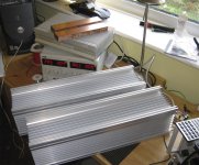
The 625VA transformer arrived to day
The 625VA transformer arrived to day
An externally hosted image should be here but it was not working when we last tested it.
I'm sorry, i don't follow you. Both output stage circuits i posted are unity gain. Yes the output transistors actually would add some gain, in fact quite a bit, however they are enclosed in a feedback loop that involves the drivers which brings the gain to unity or slightly less. The actual output of the output stage will be approximately 0.97 x the input depending on emitter resistors chosen, amplifier class (in this case Class A) & load impedance. As i say, match the drivers & there won't be a problem. If i had any doubt about this i'd hardly design & build an output stage with 3 x MJ15024 & 3 x MJ15025 driven by 3 x IRF530 & 3 x IRF9530 in the same kind of configuration.So to summarize you have two gain stages running in parallel on the output with one drive signal. When did you ever see two different gain circuits track each other? Never in my experience. Not even close to gain tracking. For high current emitter followers in parallel work much better. For gain on the output one transistor works fine. Two...not so good as it takes feedback to even make it work.
That'll do for 1 300W class A ampThe 625VA transformer arrived to day
Best of luck...I see you have the same MJ transistors as me, i bought about 50 of each recently. But then i have 6 amps to build
The actual output of the output stage will be approximately 0.97 x the input depending on emitter resistors chosen, amplifier class (in this case Class A) & load impedance. As i say, match the drivers & there won't be a problem. If i had any doubt about this i'd hardly design & build an output stage with 3 x MJ15024 & 3 x MJ15025 driven by 3 x IRF530 & 3 x IRF9530 in the same kind of configuration.
That'll do for 1 300W class A amp
I see you have the same MJ transistors as me, i bought about 50 of each recently. But then i have 6 amps to build
Hi event - and everyone
yup most of the gain as usual comes from up front... the rest is near 2:1
The MJ's are being used as PSU regulators - I chose to go to those Sankens for output. I know Mark Levinson amps tend to favour the MJ's - but the heatsink materials I got dont favour the T03 package.
The emitter resistors I have are 0.10Ω -- 0.22Ω and 0.33Ω - for experimentation at the end - see what transconductance issues I get with 2SC2922's and 2SA1216's
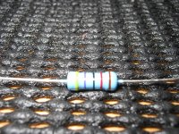
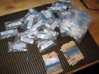
Speaking of resistors -- all the precision resistors arrived today -- so I can now start getting out of miniature experimentation and design and start doing it at full rail voltage ± 55V
....... see if I retain my eyebrows when I bias up
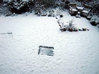
Oh yeah and the view out my workshop changed dramatically this morning too
Attachments
Last edited:
Banned
Joined 2002
There is a way round anything if you put your mind to it. I have the same problem in a way, large heatsinks already drilled to accept 2 TO-3 packages but will have 3 fitted. One way or another 3 into 2 will goI know Mark Levinson amps tend to favour the MJ's - but the heatsink materials I got dont favour the T03 package.
Douglas Self found a CFP stable quiescent current wise with 0.1 ohm emitter resistors though he was only using a single output pair. I should think that you'll find the same thing, however i'd suggest at least the 0.22 ohm until everything is working & as you want it. Then you might try the lower value & get a slight increase in efficiency.The emitter resistors I have are 0.10Ω -- 0.22Ω and 0.33Ω - for experimentation at the end - see what transconductance issues I get with 2SC2922's and 2SA1216's
Very nice to. Where did you purchase them from?Speaking of resistors -- all the precision resistors arrived today
....... see if I retain my eyebrows when I bias up
I have had quite a few explosions in my time to, luckily not for a long time though Best of luck when you decide to go for it...Nice bit of snow you have there, it's looked similar here recently to.
Likewise, i was dead chuffed when my power transistors & transformers arrived. Even more so when the PSU capacitors arrived, gotta love shopping from the comfort of your favourite chairI love goodie bags
- Status
- This old topic is closed. If you want to reopen this topic, contact a moderator using the "Report Post" button.
- Home
- Amplifiers
- Solid State
- Trying to build...an...OMG