Warning: Performing speaker THD measurements may result in permanent changes in your point of view about amplifier THD
Not necessary. It may cause a curiosity, why hearing ignores distortions caused by mechanical things, but don't forgive distortions caused by electronics. That will lead to Tube forum for answers why.
Wahab,
You are right. Q1/Q2 are indeed a diff pair, though a series connection. Voltage feedback is the mode of operation, and pnp driver current is indeed limited by the RC boostrap load resistors. And the current variation through the RC is the weak point of this design.
In truth, it is a power buffer, not an amplifier, and presented here as a curiosity, just another way of doing a power output stage.
Rod's article is good, it is consistent with most of my past designs. The road to a commercial amplifier is (and should be) littered with many different theoretical amplifiers, whose pros and cons must be carefully assessed. I am more than happy to throw up some of these ideas, but if you (and others) prefer I'm happy to remain silent.
Please remember that I make no claim to excellent design here, I am merely presenting an idea.
Hugh
Music is currently being recorded by feding the output of a microphone to an ADC and then to the input of a digital data storage device.
The data used to analyze the THD from a loudspeaker or an amplifier is obtained exactly in the same way.
Waveforms are just information, and that's what we hear. Speaker THD and amplifier THD must be the same thing.
The data used to analyze the THD from a loudspeaker or an amplifier is obtained exactly in the same way.
Waveforms are just information, and that's what we hear. Speaker THD and amplifier THD must be the same thing.
Speaker THD and amplifier THD must be the same thing.
For computer?
Sure.
For brain?
No.
Music is currently being recorded by feding the output of a microphone to an ADC and then to the input of a digital data storage device.
The data used to analyze the THD from a loudspeaker or an amplifier is obtained exactly in the same way.
Waveforms are just information, and that's what we hear. Speaker THD and amplifier THD must be the same thing.
No. A well known example is the strike sound of a church bell. When the tongue hits the bell we hear this particular strike sound but objectively it does not exist. As a matter of fact we hear a lot that objectively does not exist and we don't hear a lot details in sound fields which objectively exist.
Your assumption that human audition is in any way linear ( i.e. a linear system) such that it linearly maps an objective sound field onto a subjective impression is entirely wrong. So briefly all that matters is how it sounds and that is not a matter of thd if thd is around some %.
Wahab,
You are right. Q1/Q2 are indeed a diff pair, though a series connection. Voltage feedback is the mode of operation, and pnp driver current is indeed limited by the RC boostrap load resistors. And the current variation through the RC is the weak point of this design.
In truth, it is a power buffer, not an amplifier, and presented here as a curiosity, just another way of doing a power output stage.
Rod's article is good, it is consistent with most of my past designs. The road to a commercial amplifier is (and should be) littered with many different theoretical amplifiers, whose pros and cons must be carefully assessed. I am more than happy to throw up some of these ideas, but if you (and others) prefer I'm happy to remain silent.
Please remember that I make no claim to excellent design here, I am merely presenting an idea.
Hugh
no pun intended, hugh...
just wanted to highlight the fact that numerous topologies
where tested during the 70 s, and that few working ones did
emerge from the then inventive times...
there s 4 schematics mainly, with the three last being evolutions from
the first one..
first, a simple vas + output stage..
second, the same with an added input stage,giving
the cfb i quoted..
three, the latter with yet another device to make a differential
at the input, this is the lin that was and still the most used...
four is symetrisation of this differential, to go to a symetrical
differential...
almost all circuits are variations of these four ones, and it happens
that nothing better has been found since despite the claims
of numerous designers...
regards,
wahab
Wahab,
The fact this is a road well trod, and one so universally below par (how many commercial amps sound good?), is strong reason to continue the quest.......
I hope you are not discouraged by the conventional, which is all around us. It should be motivation to do better, to come up with something completely different. Certainly that is what drives me, despite having no more than second year undergraduate math.
Hugh
Hahfran,
Simulations won't tell you how the amp will sound, but are useful development tools. I suggest LTSpice, which is quite good and has readily available models, some on this forum. You can insert them into the model library using a text editor like Notepad; PSpice models work just fine.
Would you be happy to share your latest find?
Hugh
Hi, and how about this one mentioned by Broskie (hope not out of context in this discussion):
"...Pierre Corbeil, of Paradox Innovation in Montreal, Canada, certainly has earned his $150. EDN (Electronics Design News) magazine rewards submissions of design ideas with a check for $150 and all the glory that comes from seeing one’s name in print (or is only pixels these days?). His super clever design overcomes one of the huge problems with class-B amplifier design: getting the bias right—over time and over device heating."
CCDA & Class-AC
"...Pierre Corbeil, of Paradox Innovation in Montreal, Canada, certainly has earned his $150. EDN (Electronics Design News) magazine rewards submissions of design ideas with a check for $150 and all the glory that comes from seeing one’s name in print (or is only pixels these days?). His super clever design overcomes one of the huge problems with class-B amplifier design: getting the bias right—over time and over device heating."
.... looks like a copycat:Hi, and how about this one mentioned by Broskie (hope not out of context in this discussion):
"...Pierre Corbeil, of Paradox Innovation in Montreal, Canada,
[Terminé] Amplificateurs en classe B: et maintenant, la version Tropicalisée! - Page 2 - Forum Projets électroniques
Objectif ppm - Forum Électronique
The "Paradox" is probably the absence of "Innovation"....
Last edited:
The "Paradox" is probably the absence of "Innovation"....
.... looks like a copycat:
[Terminé] Amplificateurs en classe B: et maintenant, la version Tropicalisée! - Page 2 - Forum Projets électroniques
Objectif ppm - Forum Électronique
The "Paradox" is probably the absence of "Innovation"....
nice find, elvee....the guy at futura is very smart..
blatant copy of a canadian looter ..moreover, pierre corbeil is a typical
french name,so this guy master this language perfectly, as he s undoubtly
from french descent...
Hahfran,
Simulations won't tell you how the amp will sound, but are useful development tools. I suggest LTSpice, which is quite good and has readily available models, some on this forum. You can insert them into the model library using a text editor like Notepad; PSpice models work just fine.
Would you be happy to share your latest find?
Hugh
Ok I downloaded LTSpice but still having trouble with the results of .four they make little sense. What I found was the Blomley topology this topic is however already covered in another thread. The schematic of a Blomley curcuit by a Philips lab guy is attached ( contains some errors) it looks interesting. It avoids switching in the output stages. Further it features quiescent current stability dynamically. I don't know whether that contributes to sound however it is clear that the junction temperature varies
with power dissipation and so does the quiescent current. This won't happen in this circuit. Basically it is the same with tubes but there the plate heats up
and that hardly affects the cathode temperature.
Attachments
Ah, yes, I too have this 1984 circuit from Hartsuiker.
I vaguely remember building it many years ago but finding it no better sonically than a well set up Self DEF type II. It is certainly clever, but setting up T8 and T10 is very tetchy and liable to change with temperature unless D3/D4 exactly match the transistors for tempco. I would prefer a transistor array, all on the same die for this purpose.
The output triples have gain, at Tr2 and Tr6, and the circuit clearly shows emitter followers, darlingtons in fact, as the output devices. This may explain why it's actually very good with high capacitive loads like the ESL63, a notoriously difficult load. But there are many, many devices from start to finish, and an IC; this makes stability only possible with a lowish fb factor, at only 46dB. The circuit is also push pull throughout and this tends to null even order, whilst doing nothing for odd order harmonics.
It's elegant, but I don't believe it's the answer. A single ended approach would be better, IMHO. That is why I favour the RC concept suggested at post #27.
Cheers,
Hugh
Last edited:
es agreed the splitting TR8,10 and D3,4 is a weak point but the general idea is interesting
because it shifts the switching point away from the power transistors. One would of course avoid the IC. One may investigate whether TR8,10 could be jFETS possibly cascoded with BJTs.
However according to ole Baxandall Symmetry of a Class B the circuit is not an emitter follower. Neither is the QUAD 303 triplet an emitter follower. (Also according to Baxandall
Wireless World sept 1969 ).
The weak point of the #27 circuit is still the thermal runaway given that in my case of active speakers the heatsink size is actually less than it should be. However the max. power is determined by the dynamic range the speaker should be able to reproduce.
I see no way to feed back a current proportional to the base of Tr4 that would solve the problem of thermal runaway. Otherways it were clearly preferred.
BTW Sydney is the location of a secret emergency meeting of world bankers today....
could be the music is over.
The ideal amp...it can be done with zero bias diodes ... well these work according to zero point energy and face a great future in directly converting heat to electrictity without any meachanic involved... but zero bias. Such diodes ( maybe for a while replaced by a zero cross detector and a CMOS switch ) split positive and negative current right at the input and drive two current controlled current sources...that's it. Only current is amplified in both halves of the amp. No crossover no switching nothing of that kind yet class B. It is worth a try with CMOS audio switches such as ADG884. The zero cross detector is another story.
Yes, I'd seen that some time ago, Hawk Audio is most progressive.......
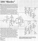
The purpose of the bootstrap around the 250uF cap is to maintain a near constant current through T1, T4 and T7. Upon the constancy of this current depends the consistent 1.3 volts drop between input and output, and hence the linearity. The bootstrap cap strongly defines the voltage at the collectors of T4 and T7, which would prevent collector of T7 going too low as it draws current from T5 on negative swings, otherwise cutting out the transistor.
The disadvantage of this circuit is the additional negative supply for the emitter of T7, which sets the quiescent. Manufacturers hate additional supplies; they really louse up the costs.
Hugh
If this topology sounds really better than the good known push pull topologies where Vbe multiplier inside (i. e. sound quality nearly than pure Class-A) this additional voltage isn't a serious problem (in opposite to very large heatsinks, neccesary for pure class-A).
Therefore the first question must be:
In which sound category I have to classify this topology: similar to the good known class AB push pull topologies with approx. 30mA or really nearly class-A ??
And why this circuit isn't to find in commercial products? Only because the additional neccesary voltage?
Last edited:
Hahfran,
I'd be interested in your attempt.... this has defied some of the best brains on the planet for fifty years.... you may be moving towards error correction feedforward, of course.
However, how about we strike a compromise? A conventional, voltage driven output stage, BUT, with no switching off at the output devices at any time? Would this suffice? It's been done, of course, a gasoline engine doing diesel tricks, and this could avoid a large Class A clunker with its grossly inefficient quiescent current.
Tief,
To answer these excellent questions you must build the circuit, subject it to measurement and listening tests over a large sample. And once you have the answers, you may be reluctant to share your findings publicly! These questions precipitate forum wars, with everyone having an opinion, but no one willing to build the prototype.....
Have a great week,
Hugh
No crossover no switching nothing of that kind yet class B. It is worth a try with CMOS audio switches such as ADG884. The zero cross detector is another story
I'd be interested in your attempt.... this has defied some of the best brains on the planet for fifty years.... you may be moving towards error correction feedforward, of course.
However, how about we strike a compromise? A conventional, voltage driven output stage, BUT, with no switching off at the output devices at any time? Would this suffice? It's been done, of course, a gasoline engine doing diesel tricks, and this could avoid a large Class A clunker with its grossly inefficient quiescent current.
Tief,
In which sound category I have to classify this topology: similar to the good known class AB push pull topologies with approx. 30mA or really nearly class-A ??
And why this circuit isn't to find in commercial products? Only because the additional neccesary voltage?
To answer these excellent questions you must build the circuit, subject it to measurement and listening tests over a large sample. And once you have the answers, you may be reluctant to share your findings publicly! These questions precipitate forum wars, with everyone having an opinion, but no one willing to build the prototype.....
Have a great week,
Hugh
Last edited:
- Status
- This old topic is closed. If you want to reopen this topic, contact a moderator using the "Report Post" button.
- Home
- Amplifiers
- Solid State
- Class B w/o crossover distortion (1975)