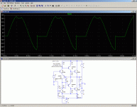
I think you do not quite understand how your own circuit works:
a) There is a reaction delay, because the hold capacitor has to charge to adapt to the new dynamic regime when it changes, and this takes time, because only a fraction of the 15mA main bias can be diverted for this purpose. I insist it is a hold capacitor; what it stores is an information: the actual Iq setting, unlike a bootstrap capacitor whose only role can be likened to an energy storage device, where the quantity itself is irrelevant provided it is sufficient (a battery would be adequate).
b) The time constant of this process is longer than the primary thermal time constants of the semiconductor devices (the dice), and anyway it adds a large amount of dissipation to that caused by the class B operation. But at the same time, it remains servoed, and doesn't run the risk of going into the usual thermal runaway, say like a simple class B amplifier without emitter resistors.
IMHO, the main drawback of this amplifier is its inability to reach the full power without adapting the operating point.
If it could cover the whole dynamic range with the initial Iq setting, it would be near-ideal, as the current servoing scheme seems to work well, but does not cover the whole span.
This might be corrected, perhaps by substituting MOS output devices.
No there is only at the startup the initial load of the cap that is why one has to delay the sine source for 1 sec. It needs not to the operating point adapt thereafter. LTSpice does not provide a burst source so one cannot simulate. Further no, a change of iq due to junction temp is not servoed without emitter resistors. But anyway it should be very simple to built with modern devices.
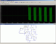
LTspice can provide tone bursts in a number of ways:
Here is one.
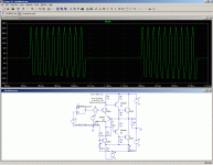
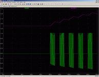
Picture 2 shows the detail, and picture 3 shows also the voltage across the capacitor.
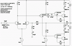
When the average level of conduction of Q2 increases, the duty cycle of D1's conduction also increases, diverting the 15mA bias away from Q7 more of the time.
This decreases the charge going into C1, and corrects the Iq through Q2 (and Q1).
Here is one.
Picture 2 shows the detail, and picture 3 shows also the voltage across the capacitor.
It is, because the level of charge of the capacitor (which sets the quiescent current) relies on the splitting factor of the switching modulator formed by D1, Q2 and Q7.Further no, a change of iq due to junction temp is not servoed without emitter resistors
When the average level of conduction of Q2 increases, the duty cycle of D1's conduction also increases, diverting the 15mA bias away from Q7 more of the time.
This decreases the charge going into C1, and corrects the Iq through Q2 (and Q1).
Attachments
I have now built one all free wired on heatsink ( all trans are mounted to heatsink)
in that real model replacing D6 that sets the bias of the CS with a red LED Vf=1.36 Volts
improved the performance incredibly. With unregulated supply of 36 volts the amp puts out
30 v peak to peak into an 8 Ohms res at an incredibly low thd ( possibly below the accuracy of the soundcard based spectrum analyser ) . At any frequency between 20/s and 10000/s. Without the added emitter resistors and feedback from these thermal stability is EXTREMELY poor - not usable. After 20 seconds at full load the iq was at 300mA and rapidly increasing. It could be the thermal coupling of the rush transistors would bring iq down after a while but I turned power off. With the additional r's and feedback iq is reasonably controlled.
BUT: when it drives a real 8 Ohms speaker in a closed enclosure above res freq when it is mainly inductive at 20 volts pp the thd is 47% !! It is all odd harmonics.
Even worse with a 2 1/2 way speaker with some hefty crossover design. Here it ends up at about 15 volts pp after that thd increases steeply. There is no oscillation, however.
It appears this topology realised as a real circuitry and driving a real complex load is of little value it is worse than any simple emitter follower cascade.
Amazingly enough it works perfectly when driving a capacitive load...6.2 Ohms paralleled 220nF ... it just cannot stand inductive loads. In the case of capacitive the source impedance has neglegible influence ( I use a tube Wien bridge that can output 40 volts pp but has a high real part of impendance about 10 kOhms and some 200 pF parallel) in case of inductive buffering the source with an emitter follower appears better. Strange stuff.
Bootstrapped concertina?
I slightly disagree the placement of your Schottky. That would be more effective
to combine the collector current of Q2 with the emitter current of Q4 and run
both thru the same Schottky (and maybe 0.1R) to the output. Giving this Sziklai
pair an overall more square law curve and less dependence upon temperature.
You should compliment with a second Schottky+.1R from Q1+Q3 to the top rail.
Furthermore, the base of Q7 could connect direct to the -35 rail, and ditch R5
and D2 voltage reference???
Last edited:
Ok got it fixed. The original circuit by Vish appears to suffer from the direct feedback to the base of one Rush cascode. That will in practice hardly ever work as its sensitivity to
load impedance is too high. It appears that with the old technology for ex. the single diffused 2N3055 this had not been a big issue.
Anyway it looks good now.
It is only a kind of natural evolution to redesign the circuit as such that it becomes symmetrical. The Rush is now driven at the common emitters and the feedback goes symmetrically to both bases.
No idea what Allison refers to. All I wanted is an amp for my active speaker project from which I need about 10 identical amps which do not require any fiddling with Vbe multiplier setting in terms of temp nor any iq setting. This vish topology appeared to be the perfect candidate. Moreover it is sparing hefty requirements in terms of heatsink thermal resistance as in an active speaker the size of heatsinks is predetermined by enclosure design while on the other side the max power is determined by amplitude statistics of music and efficienyInput between the emitters sounds like Allison.
of speakers.
I see that the simple Vish topology requires some more engineering.
A major drawback in term so unconditional stability vs. complex load appears to be the voltage feedback. Another weak point is the temp dependent current source. I guess in the Vish paper this CS is thought as a template.
But I am confident I can fix these weak points.
Sim result of the original Visch circuit on an inductive load are .....
Interesting!
The circuit requires a carefully engineered output filter Boucherot doesn't suffice. Further it requires compensation.
I made a big mistake when i mounted the CS on the heatsink...for mechanical stability.
Dead wrong. The current source must be independent of temp. Since active speaker require a small extra PSU anyway for automatic turn on this could be used to heat up the CS at a constant temp , well regulated with 1° error. A trans for heating, some temperature dependent resistor and an opamp will do.
Dead wrong. The current source must be independent of temp. Since active speaker require a small extra PSU anyway for automatic turn on this could be used to heat up the CS at a constant temp , well regulated with 1° error. A trans for heating, some temperature dependent resistor and an opamp will do.
It is only a kind of natural evolution to redesign the circuit as such that it becomes symmetrical. The Rush is now driven at the common emitters and the feedback goes symmetrically to both bases.
Search this forum for Keantoken's thread and keyword "Allison"
Ok meanwhile I sim another idea - input and feedback to the emitters of Rush.
Btw a certain Charles Hansen who happens to produce Ayre amps claims that local feedback in the power stage produces more distortion then without any feedback at all.
Interesting are his remarks an JFETS these should be used throughout cascaded with BJTs as this cascade produces less distortion than anything even triodes. I wonder from where does he get power jFETs?
Allison in sim is as well sensitive to reactive loads.
I made a simple "current dumping" circuit and wow...it drives all reactive loads without any change in thd which is measured 1% ( can be improved) there is also no change in the harmonics spectrum. Interesting. Disturbing is unexpected hf noise.
I made a simple "current dumping" circuit and wow...it drives all reactive loads without any change in thd which is measured 1% ( can be improved) there is also no change in the harmonics spectrum. Interesting. Disturbing is unexpected hf noise.
Surprise surprise...I did a reading of the thd with a software spectrum analyser for various frequencies. The Vish drives a 2 1/2 way speaker. The out put voltage is constant vs. frequency 30 v pp about 14 Watts/8 ohms. The thd and the harmonics spectrum varies widely with frequency!
There is unsurprisingly a minimum when the (well known) impedance of the speaker is almost real. This is however the minimum impedance of the speaker about 4 ohms.
So at max current there is the lowest distortion. Almost unmeasurable. It rises sharply when the impedance has imaginary parts at different frequencies.
This is interesting and instead of designing for minimum thd on a real load at 1 kHz the design objective should be to avoid frequency dependent distortion with reactive load.
I suspect that commercial amps won't be that much better.
Last edited:
- Status
- This old topic is closed. If you want to reopen this topic, contact a moderator using the "Report Post" button.
- Home
- Amplifiers
- Solid State
- Class B w/o crossover distortion (1975)
